SUPPLEMENTAL RESTRAINTS
Supplemental Restraints Wiring Diagram (1 of 2) for Hummer H3 2006

List of elements for Supplemental Restraints Wiring Diagram (1 of 2) for Hummer H3 2006:
- Accessory switch
- Airbag fuse 27 10a
- G310
- G310 (mounted under left side of passenger seat)
- Grd
- Hot w/ run/crank relay energized
- I/p stage 1-h
- I/p stage 1-l
- I/p stage 2 l
- I/p stage 2-h
- Ign 1 +
- Inflatable restraint i/p module
- Inflatable restraint passenger airbag on/off indicator
- Inflatable restraint sensing/diagnostic module (sdm) (beneath lower console)
- Inflatable restraint steering wheel module
- Inflatable restraint steering wheel module coil (steering wheel)
- L asf +
- L asf sig
- L asf-h
- L asf-l
- L belt sw
- L efs +
- L efs sig
- L pretens-h
- L pretens-l
- Left front seat belt pretensioner (at left inner "b" pillar)
- Nca
- Passenger seat belt indicator
- Pnk
- Pos rtrn
- Pos sensor-h
- R asf +
- R asf sig
- R asf-h
- R asf-l
- R belt sw
- R efs +
- R efs sig
- R pretens-h
- R pretens-l
- Red
- Right front seat belt pretensioner (at right inner "b" pillar)
- S205
- Serial
- Shorting bar
- Stage 1
- Stage 1-h
- Stage 1-l
- Stage 2
- Stage 2 l
- Stage 2-h
- Tan
- Underhood fuse block (above left front wheel well)
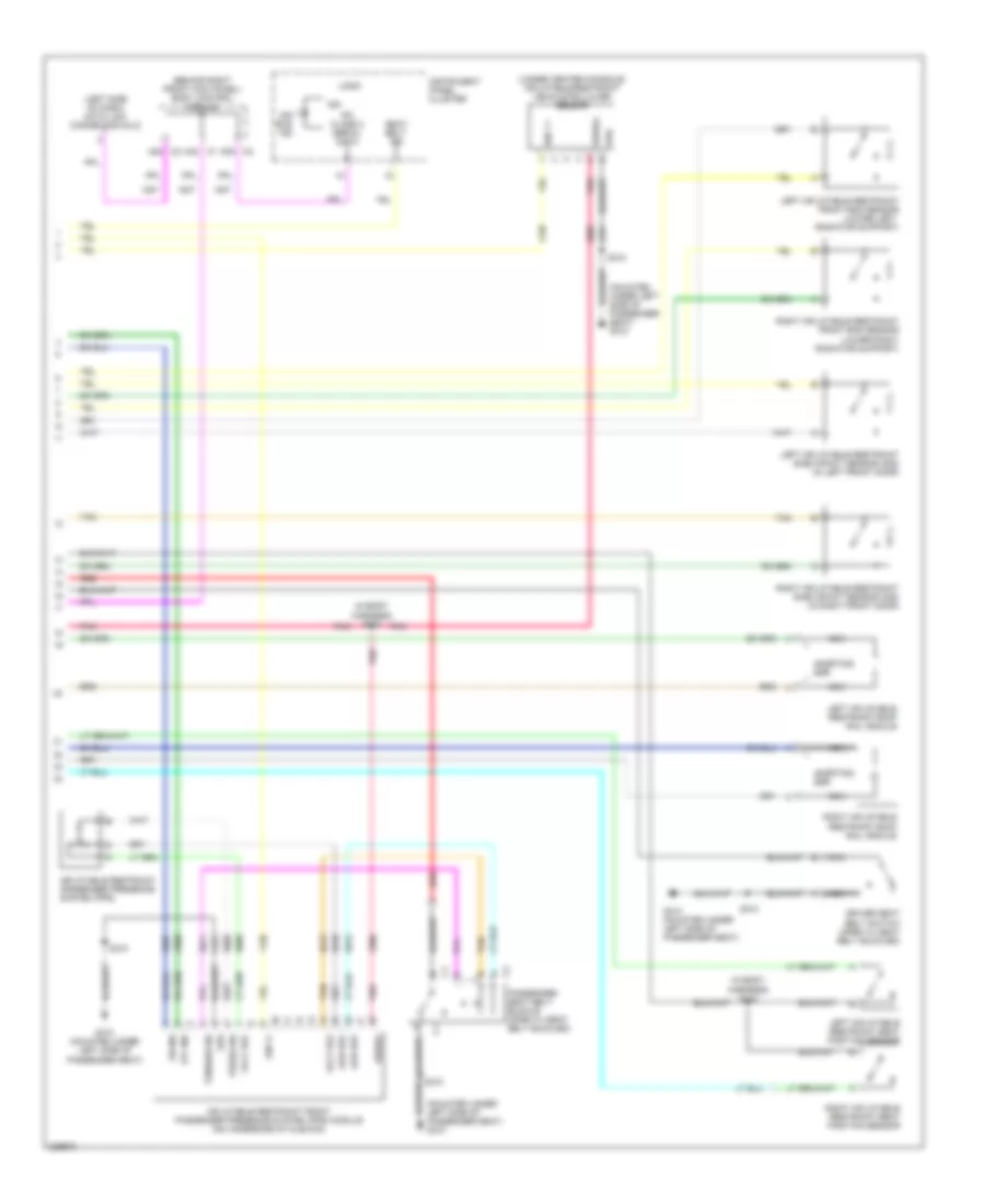
Supplemental Restraints Wiring Diagram (2 of 2) for Hummer H3 2006
List of elements for Supplemental Restraints Wiring Diagram (2 of 2) for Hummer H3 2006:
- (behind right front kick panel) body control module
- (in body harness) s323
- (in body harness) s344
- (left side of dash) data link connector (dlc)
- (mounted under left side of passenger seat) g310
- (under center console) inflatable restraint vehicle rollover sensor
- A38 c2
- A39 c2
- A42 c1
- Air bag ind
- Driver seat belt switch (open w/ seat belt buckled)
- G310 (mounted under left side of passenger seat)
- Grd
- Ign
- Ign 1 +
- Ign 1+
- Inflatable restraint front passenger presence system (pps) module (on underside of cushion)
- Inflatable restraint passenger presence system (pps)
- Instrument panel cluster
- Ipc class 2 serial data
- Left inflatable restraint front end sensor (lower left radiator support)
- Left inflatable restraint roof rail module
- Left inflatable restraint seat position sensor
- Left inflatable restraint side impact sensor (sis) (in left front door)
- Logic
- Low ref
- Nca
- Off ind
- On ind
- Passenger seat belt buckle (open w/ seat belt buckled)
- Pnk
- Press sig
- Red
- Right inflatable restraint front end sensor (lower right radiator support)
- Right inflatable restraint roof rail module
- Right inflatable restraint seat position sensor
- Right inflatable restraint side impact sensor (sis) (in right front door)
- S310
- Seat belt ind
- Serial
- Shorting bar
- Tan
- Tension sig
- Volt ref