INSTRUMENT CLUSTER
Instrument Cluster Wiring Diagram for Hummer H3 2006
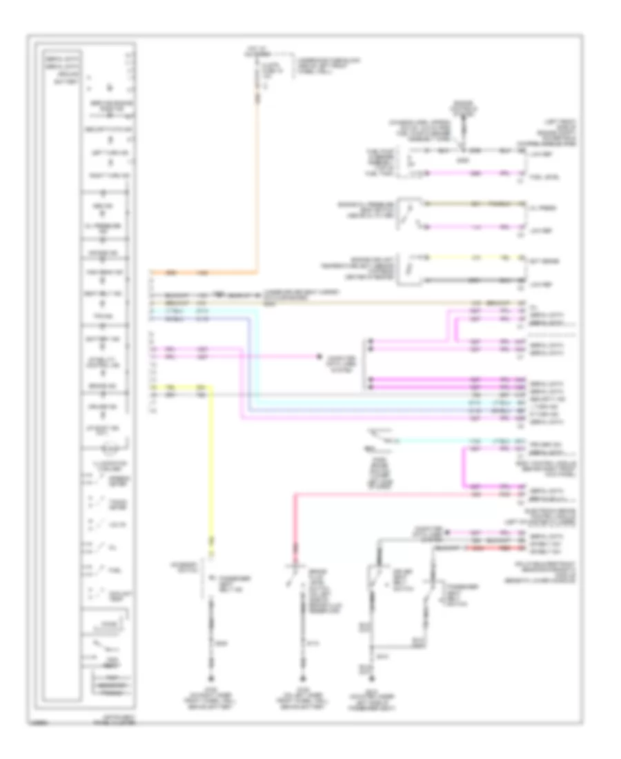
List of elements for Instrument Cluster Wiring Diagram for Hummer H3 2006:
- (chassis harn, approx 22.5 cm (8.9 in) from fuel pump & sender assembly conn)
- (left front side of engine compt) powertrain control module (pcm)
- (under driver seat carpet, on floor board) g300
- A19
- A31
- A38
- A39
- A41
- A42
- A44
- A47
- Abs ind
- Accesory switch
- Air bag ind
- B nca
- Battery
- Battery ind
- Body control module (behind right front kick panel)
- Brake fluid level switch (on left side of brake fluid reservoir)
- Brake ind
- Brk fluid lvl
- Chime
- Clstr fuse 19 10a
- Computer data lines system
- Coolant temp
- Cruise ind
- Dr belt sw
- Driver seat belt switch
- Ect sense
- Electronic brake control module (left of master cylinder)
- Engine controls system
- Engine coolant
- Engine oil pressure (eop) switch (above oil filter)
- Fuel
- Fuel level
- Fuel pump & sender assembly (top of fuel tank)
- G105 (on left inner front wheel well, behind battery
- G106 (on right inner front wheel well, behind battery
- G310 (mounted under left side of passenger seat)
- Ground
- High beam ind
- Hot at all times
- Illumination (4 bulbs)
- Inflatable restraint sensing/diagnostic module (beneath lower console)
- Instrument panel cluster
- L turn ind
- Left turn ind
- Low ref
- Mil
- Nca
- Odometer
- Oil
- Oil press
- Oil pressure ind
- Park brake switch (lower left side of dash)
- Passenger seat belt ind
- Passenger seat belt switch
- Pnk
- Prk brk sw
- Prnd321
- R turn ind
- Red
- Right turn ind
- S110
- S205
- S251
- S310
- S359
- Seat belt ind
- Security ind
- Security/ctd ind
- Serial data
- Service engine soon ind
- Speedo- meter
- Stability control ind
- Tacho- meter
- Temperature (ect) sensor (top rear center of engine)
- Tpm ind
- Trip
- Trip reset
- Underhood fuse block (above left front wheel well)
- Up shift ind (m/t)
- Volts
 English