AIR CONDITIONING
3.8L
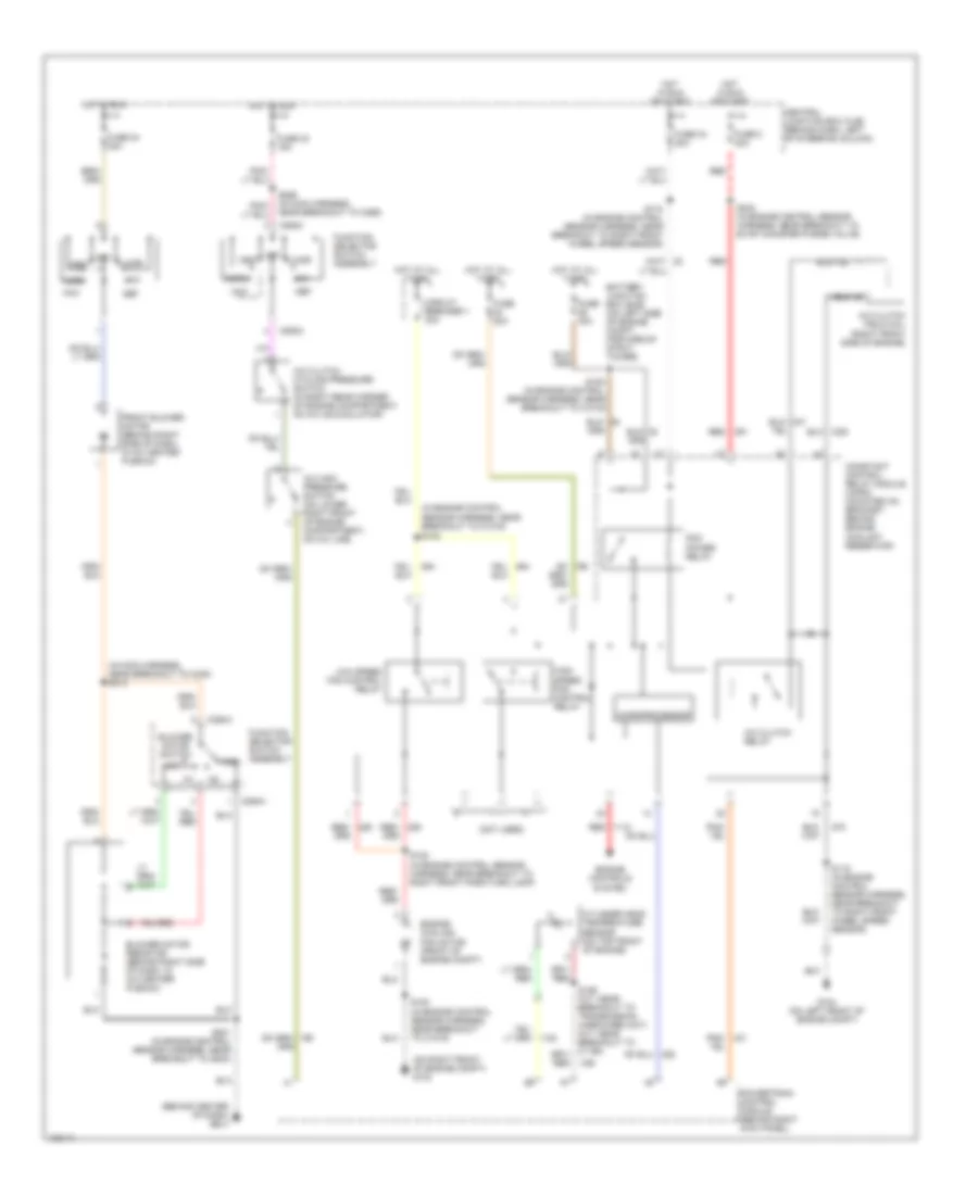
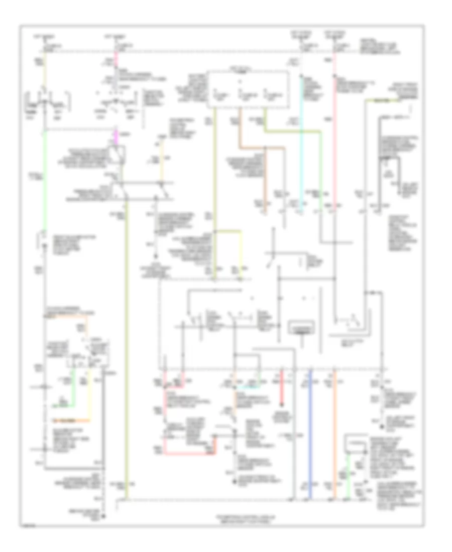
3.8L, Manual A/C Wiring Diagram for Ford Mustang GT 2004

List of elements for 3.8L, Manual A/C Wiring Diagram for Ford Mustang GT 2004:
- (behind center of dash) g204
- (in engine control sensor harness, near breakout to c1019) s102
- (in main harness, near breakout to c238) s213
- (not used)
- (on right front of engine compt) g103
- A/c clutch cycling pressure switch (in right rear corner of engine compartment, on a/c accumulator)
- A/c clutch field coil (right front side of engine)
- A/c clutch relay
- A/c high pressure switch (on lower right front of engine compartment, on a/c line)
- Battery junction box (bjb) (on left side of engine compt, forward of strut tower)
- Blower motor resistor (behind right side of dash, in a/c heater plenum)
- Blower motor switch
- C294a
- C294c
- Central junction box (cjb) (behind dash, left of steering column)
- Circuit breaker 1 30a
- Constant control relay module (ccrm) (mounted on bracket, behind engine coolant reservoir)
- Cylinder head temperature sensor (on top front of engine)
- Def
- Engine controls system
- Engine cooling fan motor (front of engine compt)
- Floor
- Front blower motor (behind right side of dash, in a/c heater plenum)
- Function selector switch assembly
- Fuse 2 20a
- Fuse 20a
- Fuse 23 15a
- Fuse 24 30a
- Fuse 30a
- Fuse 34 20a
- G104 (on left front of engine compt)
- High
- High speed fan control relay
- Hot at all times
- Hot in run
- Hot in run or start
- Low
- Low speed fan control relay
- Max
- Microprocessor
- Mix
- Norm
- Off
- Pcm power relay
- Pnk/
- Powertrain control module (behind right kick panel)
- Red
- Red/
- S100 (in engine control sensor harness, near breakout to c1019)
- S108 (in engine control sensor harness, near breakout to c1019)
- S115 (in engine control sensor harness, near breakout to right front wheel speed sensor)
- S122 (in engine control sensor harness, near breakout to right front park/turn lamp)
- S174 (in engine control sensor harness, near breakout to right front wheel speed sensor)
- S201 (in engine control sensor harness, near breakout to g203)
- S234 (in engine control sensor harness, near breakout to evap canister purge valve)
- S256 (in main harness, near breakout to c265)
- Vent
3.9L
3.9L, Manual A/C Wiring Diagram for Ford Mustang GT 2004
List of elements for 3.9L, Manual A/C Wiring Diagram for Ford Mustang GT 2004:
- (behind center of dash) g204
- (in engine control sensor harness, near breakout to c1019) s102
- (in main harness, near breakout to c238) s213
- (not used)
- (on right front of engine compt) g103
- A/c clutch cycling pressure switch (in right rear corner of engine compartment, on a/c accumulator)
- A/c clutch field coil (right front side of engine)
- A/c clutch relay
- A/c high pressure switch (on lower right front of engine compartment, on a/c line)
- Battery junction box (bjb) (on left side of engine compt, forward of strut tower)
- Blower motor resistor (behind right side of dash, in a/c heater plenum)
- Blower motor switch
- C294a
- C294c
- Central junction box (cjb) (behind dash, left of steering column)
- Circuit breaker 1 30a
- Constant control relay module (ccrm) (mounted on bracket, behind engine coolant reservoir)
- Cylinder head temperature sensor (on top front of engine)
- Def
- Engine controls system
- Engine cooling fan motor (front of engine compt)
- Floor
- Front blower motor (behind right side of dash, in a/c heater plenum)
- Function selector switch assembly
- Fuse 2 20a
- Fuse 20a
- Fuse 23 15a
- Fuse 24 30a
- Fuse 30a
- Fuse 34 20a
- G104 (on left front of engine compt)
- High
- High speed fan control relay
- Hot at all times
- Hot in run
- Hot in run or start
- Low
- Low speed fan control relay
- Max
- Microprocessor
- Mix
- Norm
- Off
- Pcm power relay
- Pnk/
- Powertrain control module (behind right kick panel)
- Red
- Red/
- S100 (in engine control sensor harness, near breakout to c1019)
- S108 (in engine control sensor harness, near breakout to c1019)
- S115 (in engine control sensor harness, near breakout to right front wheel speed sensor)
- S122 (in engine control sensor harness, near breakout to right front park/turn lamp)
- S174 (in engine control sensor harness, near breakout to right front wheel speed sensor)
- S201 (in engine control sensor harness, near breakout to g203)
- S234 (in engine control sensor harness, near breakout to evap canister purge valve)
- S256 (in main harness, near breakout to c265)
- Vent
4.6L
4.6L, Manual A/C Wiring Diagram for Ford Mustang GT 2004
List of elements for 4.6L, Manual A/C Wiring Diagram for Ford Mustang GT 2004:
- (4.6l supercharged: near breakout to barometric absolute pressure sensor) (4.6l sohc, 4.6l dohc: near breakout to c1148)
- (behind center of dash) g204
- (in engine control sensor & fuel charge harness, near breakout to c133) s180
- (in main harness, near breakout to c238) s213
- (on left front of engine compartment) g104
- (on right front of engine compartment) g103
- (right front side of engine) a/c clutch field coil
- 4.6l sohc
- A/c clutch cycling pressure switch (in right rear corner of engine compartment, on a/c accumulator)
- A/c clutch relay
- Auxiliary fuse box (on right side of engine compt, on fender)
- Battery junction box (bjb) (on left side of engine compt, forward of strut tower)
- Blower motor resistor (behind right side of dash, in a/c heater plenum)
- Blower motor switch
- C294a
- C294c
- Central junction box (cjb) (behind dash, left of steering column)
- Circuit breaker 30a
- Constant control relay module (ccrm) (mounted on bracket, behind engine coolant reservoir)
- Def
- Dual pressure switch (right front of engine compartment)
- Engine controls system
- Engine coolant temperature (ect) sensor (4.6l supercharged, 4.6l dohc: on top left front of engine) (4.6l sohc: on top right front of engine, front of fuel injector 1)
- Engine cooling fan motor (front of engine compartment)
- Floor
- Front blower motor (behind right side of dash, in a/c heater plenum)
- Function selector switch assembly
- Fuse 1 50a
- Fuse 2 20a
- Fuse 23 15a
- Fuse 24 20a
- Fuse 24 30a
- Fuse 26 30a
- Fuse 34 20a
- G103 (on right front of engine compartment)
- High m2
- High speed fan control relay
- Hot at all times
- Hot in run
- Hot in run or start
- Low
- Low speed fan control relay
- Max
- Micropro- cessor
- Mix
- Norm
- Off
- Pcm power relay
- Powertrain control module (behind right kick panel)
- Red
- S100 (near breakout to mass air flow sensor)
- S102 (4.6l supercharged: near breakout to intake air temperature sensor) (4.6l sohc, 4.6l dohc: near breakout to c1147)
- S108 (in engine control sensor harness, near breakout to mass air flow sensor)
- S115 (near breakout to right front wheel speed sensor)
- S122 (near breakout to constant control relay module)
- S130
- S201 (in engine control sensor harness, near breakout to g203)
- S234 (near breakout to evap canister purge valve)
- S256 (in main harness, near breakout to c265)
- S266 (in main harness, near breakout to c260)
- Vent
- Vref