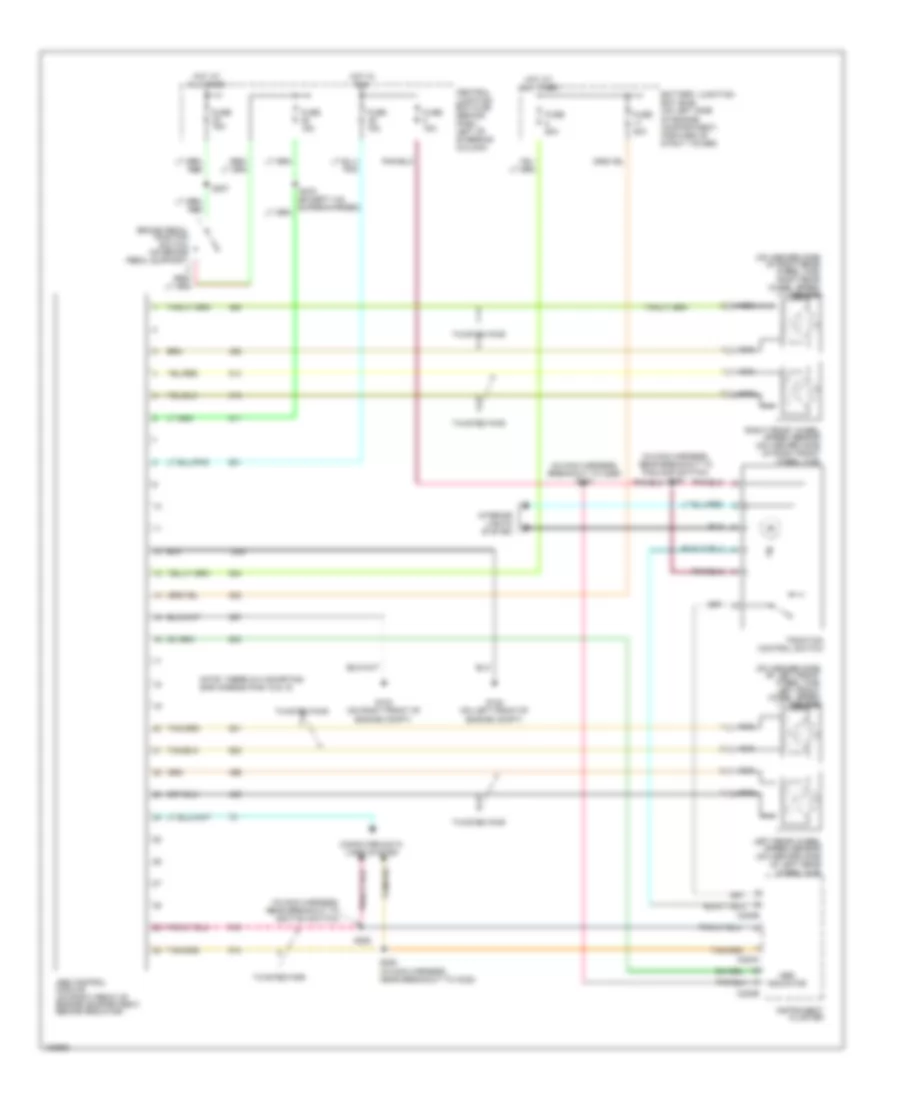
ANTI-LOCK BRAKES
Anti-lock Brakes Wiring Diagram for Ford Mustang GT 2004
List of elements for Anti-lock Brakes Wiring Diagram for Ford Mustang GT 2004:
- (in main harness, breakout to c265) s257
- (in main harness, near breakout to foglamp switch) s284
- (in main harness, near breakout to ignition switch)
- (on inboard side of left front wheel hub) left front wheel speed sensor
- (on inboard side of right rear wheel hub) right rear wheel speed sensor
- Abs control module (on right front of engine compartment, behind radiator)
- Abs indicator
- Battery junction box (bjb) (on left side of engine compartment, forward of strut tower)
- Brake pedal position switch (on brake pedal support)
- C220a
- C220b
- Central junction box (cjb) (behind dash, left of steering column)
- Computer data lines system
- Fuse 15a
- Fuse 20a
- Fuse 50a
- G102 (on left front of engine compt)
- G103 (on right front of engine compt)
- Hot at all times
- Hot in run
- Instrument cluster
- Interior lights system
- Left rear wheel speed sensor (on inboard side of left rear wheel hub)
- Nca
- Note: there is a shorting bar across pins 15 & 16
- Right front wheel speed sensor (on inboard side of right front wheel hub)
- S207
- S252
- S253 (in main harness, near breakout to c238)
- Traction control switch
- Twisted pair
 English