SUPPLEMENTAL RESTRAINTS
Supplemental Restraints Wiring Diagram for Ford Mustang GT 2004
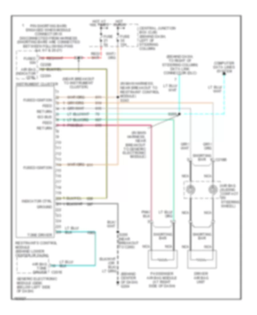
List of elements for Supplemental Restraints Wiring Diagram for Ford Mustang GT 2004:
- (behind center of dash) g204
- (behind dash, to right of steering column) data link connector (dlc)
- (in main harness, near breakout to generic electronic module)
- (in main harness, near breakout to restraint control module) s243
- (near breakout to instrument cluster)
- (or
- Air bag
- Air bag sliding contact (in steering wheel)
- Air bag tone driver
- C201e
- C218b
- C220a
- C220b
- Central junction box (cjb) (behind dash, left of steering column)
- Computer data lines system
- Driver air bag unit
- Feed
- Fuse 15a
- Fuse 5a
- Fused ign
- Fused ignition
- Generic electronic module (gem) (below left side of dash)
- Ground
- Hot at all times
- Hot in run
- Indicator ctrl
- Instrument cluster
- Iso bus
- Nca
- Passenger air bag module (at right side of dash)
- Pin shorting bars engaged when module connector is disconnected from harness (shorting bars are connected between following pins: 3-4, 6-7 & 20-21)
- Restraints control module (behind lower center of dash)
- Return
- S205 (near breakout to c260)
- S255
- S259
- Shorting bar
- Tone driver
 English