CRUISE CONTROL
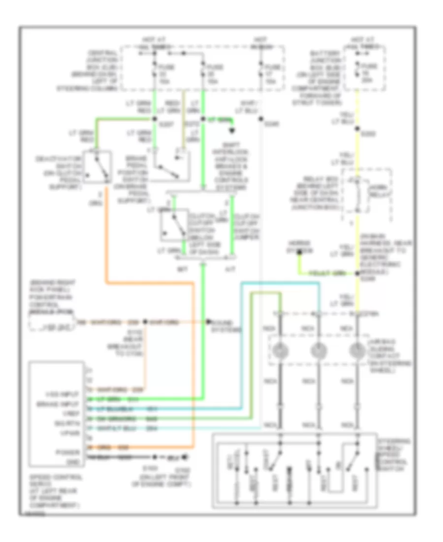
Cruise Control Wiring Diagram for Ford Mustang GT 2004
List of elements for Cruise Control Wiring Diagram for Ford Mustang GT 2004:
- (behind right kick panel)
- (in main harness, near breakout to generic electronic module) s249
- A/t
- Accel set/
- Air bag sliding contact (in steering wheel)
- Battery junction box (bjb) (on left side of engine compartment, forward of strut tower)
- Brake input
- Brake pedal position switch (on brake pedal support)
- C218a
- Central junction box (cjb) (behind dash, left of steering column)
- Clutch cutoff switch (below left side of dash)
- Coast
- Deactivator switch (on clutch pedal support)
- Fuse 15a
- Fuse 20a
- G102 (on left front of engine compt)
- Gnd
- Horn relay
- Horns system
- Hot at all times
- Hot in run
- M/t
- Nca
- Off
- Power
- Powertrain control module (pcm)
- Relay box (behind left side of dash, near central junction box)
- Rest
- Resume
- S103
- S112 (near breakout to c134)
- S202
- S207
- S245
- S272
- Shift interlock, anti-lock brakes & engine controls systems
- Sig rtn
- Sound systems
- Speed control servo (at left rear of engine compartment)
- Steering wheel/ speed control switch horn
- Vpwr
- Vref
- Vss input
- Vss out
 English