POWER DISTRIBUTION
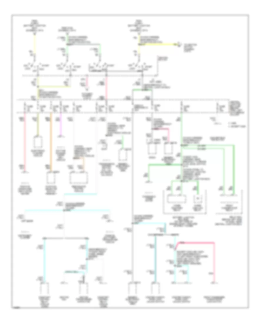
Power Distribution Wiring Diagram (1 of 3) for Ford Mustang GT 2004

List of elements for Power Distribution Wiring Diagram (1 of 3) for Ford Mustang GT 2004:
- (3.8l/3.9l: near breakout to c1019) (4.6l: near breakout to mass airflow sensor) s108
- (4.6l sohc, 4.6l dohc: near breakout to c1147)
- (4.6l super charged) (on right side of engine compt, on fender)
- (except mach 460, mach 1000: near breakout to convertible top motor) (mach 460, mach 1000: near breakout to front subwoofer amplifier) s409
- (except mach 460, mach 1000: near breakout to left front subwoofer) (mach 460, mach 1000: near breakout to left front speaker)
- (in body main harness, near breakout to generic electronic module) s269
- (in main harness, near breakout to c260) s270
- (in main harness, near breakout to main light switch) s233
- (in main harness, near breakout to main light switch) s242
- (near breakout to c146) s107
- (near breakout to c192) s105
- (near breakout to rear window defrost relay) s278
- (near breakout to relay box) s202
- 3.8l
- 4.6l
- Abs control module
- Auxiliary fuse box
- Battery
- Battery junction box (bjb) (on left side of engine compt, forward of strut tower)
- C102c c102a
- C201a
- C201b
- C202a
- C4157a
- C4158a
- C4159a
- C4160a
- C537 c508
- Central junction box (cjb) (behind dash, left of steering column)
- Charge air cooler pump relay
- Circuit breaker 30a
- Constant control relay module (ccrm)
- Convertible
- Convertible top lower relay
- Convertible top raise relay
- Data link connector (dlc)
- Daytime running lamps (drl) module
- Driver's seat adjust switch
- Electronic flasher module
- Except convertible
- Exterior rear view mirror switch
- Fog lamp relay
- Front cigar lighter
- Front passenger window/ door lock switch
- Fuse 10a
- Fuse 15a
- Fuse 20a
- Fuse 25a
- Fuse 30a
- Fuse 40a
- Fuse 50a
- G203 (behind center of dash)
- Generator
- Generic electronic module (gem)
- Horn relay
- Luggage compt lid release relay
- Luggage compt lid release switch
- Main light switch
- Master window/ door lock/ unlock switch
- Multi- function switch
- Nca
- Park lamp relay
- Power point
- Rear window defrost relay
- Red
- Relay box (behind left side of dash, near central junction box)
- S102
- S109 (near breakout to c192)
- S127 (in breakout to battery junction box)
- S268 (in main harness, near breakout to relay box)
- Starter motor
- Starter relay
- Subwoofer amplifier (luggage compt left inboard)
- Subwoofer amplifier (luggage compt left outboard)
- Subwoofer amplifier (luggage compt right inboard)
- Subwoofer amplifier (luggage compt right outboard)
- To fuse 27 (diagram 3 of 3)
- To ignition switch (diagram 2 of 3)
- To splice s215 (diagram 2 of 3)
- To splice s217 (diagram 2 of 3)
- W/ 4.6l dohc
- W/o 4.6l dohc
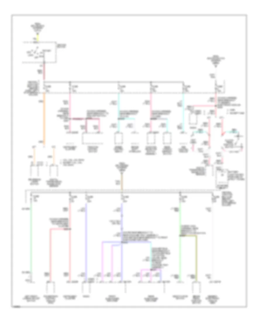
Power Distribution Wiring Diagram (2 of 3) for Ford Mustang GT 2004
List of elements for Power Distribution Wiring Diagram (2 of 3) for Ford Mustang GT 2004:
- (except mach 460, mach 1000: near breakout to left front subwoofer) (mach 460, mach 1000: near breakout to left front speaker) s505
- (in dash panel to headlamp junction harness, near breakout to battery junction box) s113
- (in main harness, near breakout to c260) s265
- (in main harness, near breakout to c260) s267
- (in main harness, near breakout to generic electronic module) s262
- (in main harness, near breakout to ignition switch) s215
- (in main harness, near breakout to ignition switch) s217
- (in main harness, near breakout to relay box) s225
- (in main harness, near breakout to restraint control module) s243
- (near breakout to central junction box) s264
- (near breakout to right front wheel speed sensor) s174
- (not used)
- 3.8l
- 4.6l
- Acc
- Battery junction box (bjb) (on left side of engine compt, forward of strut tower)
- C201a
- C201e
- C220b
- C290a
- C290d
- C294c
- Central junction box (cjb) (behind dash, left of steering column)
- Circuit breaker 43 20a
- Constant control relay module (ccrm)
- Convertible
- Convertible top switch
- Coupe
- Daytime running lamps (drl) module
- Electronic flasher module
- Except m460
- From fuse 4 (battery junction box) (diagram 1 of 3)
- From fuse 5 (battery junction box) (diagram 1 of 3)
- From s109 (diagram 1 of 3)
- Front passenger window/door lock switch
- Front washer pump relay
- Function selector switch assembly
- Fuse 15a
- Fuse 20a
- Fuse 2a
- Fuse 30a
- Generic electronic module (gem)
- Ignition coil
- Ignition switch
- Ignition transformer capacitor
- Instrument cluster
- Lock
- M460
- Master window/ door lock/ unlock switch
- Nca
- Off
- Passive anti-theft transceiver module
- Pnk
- Positive crankcase ventilation heater
- Radio
- Relay box (behind left side of dash, near central junction box)
- Restraints control module
- Run
- S211 (in main harness, near breakout to ignition switch)
- Sta
- Start
- To fuse 6 diagram (3 of 3)
- To ignition switch (diagram 3 of 3)
- Transmission control switch (3.8l, 3.9l, 4.6l sohc & 4.6l dohc)
- Windshield wiper motor
- Wiper high/low relay
- Wiper run/park relay
Power Distribution Wiring Diagram (3 of 3) for Ford Mustang GT 2004
List of elements for Power Distribution Wiring Diagram (3 of 3) for Ford Mustang GT 2004:
- (convertible: near breakout to convertible top motor) (coupe: near breakout to rear package tray assembly) s431
- (in body main harness, near breakout to deactivator switch) s207
- (in main harness, near breakout to c134) s245
- (in main harness, near breakout to c265) s256
- (in main harness, near breakout to c265) s257
- (in main harness, near breakout to foglamp switch) s284
- (in main harness, near breakout to generic electronic module) s239
- (in main harness, near breakout to instrument cluster)
- (not used)
- 3.8l, 3.9l, 4.6l dohc
- 4.6l dohc
- A/t
- Abs control module
- Acc
- B a
- Battery junction box (forward of strut tower)
- Brake pedal position switch
- Brake shift interlock
- C1131 c1131
- C201b
- C220b
- C290a
- C290d
- C290d c290a
- C294c
- C4108a
- C4109a
- Central junction box (cjb) (behind dash, left of steering column)
- Clutch pedal position switch
- Deactivator switch
- Digital transmission range (dtr) sensor
- Except 3.8l, 3.9l,
- Except m460
- From ignition switch (diagram 2 of 3)
- From splice s215 (diagram 2 of 3)
- From splice s260 (diagram 1 of 3)
- Front subwoofer amplifier
- Function selector switch assembly
- Fuse 15a
- Fuse 20a
- Fuse 30a
- Fuse 5a
- Generic electronic module (gem)
- Ignition switch
- Instrument cluster
- Left front, lumbar adjust switch
- Lock
- M/t
- M460
- Nca
- Off
- Powertrain control module (pcm)
- Radio
- Rear package tray assembly) (convertible:near breakout to front subwoofer amplifier) s432
- Rear subwoofer amplifier
- Rear window defrost switch
- Reversing lamps switch
- Run
- S259
- Speed control servo
- Start
- Starter relay
- Traction control switch