
HORN
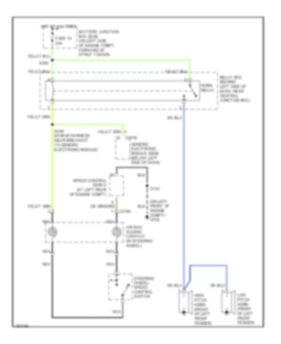
Horn Wiring Diagram for Ford Mustang GT 2004
List of elements for Horn Wiring Diagram for Ford Mustang GT 2004:
ANTI-LOCK BRAKESAIR CONDITIONINGANTI-THEFTCOOLING FANCOMPUTER DATA LINESDEFOGGERSBODY CONTROL MODULESCRUISE CONTROLEXTERIOR LIGHTSENGINE PERFORMANCEHEADLIGHTSGROUND DISTRIBUTIONHORNPOWER DOOR LOCKSINTERIOR LIGHTSPOWER MIRRORSINSTRUMENT CLUSTERPOWER DISTRIBUTIONPOWER WINDOWSPOWER TOP/SUNROOFPOWER SEATSSUPPLEMENTAL RESTRAINTSSHIFT INTERLOCKTRUNK, TAILGATE, FUEL DOORSTARTING/CHARGINGWARNING SYSTEMSTRANSMISSIONRADIOWIPER/WASHER