ENGINE PERFORMANCE
3.8L
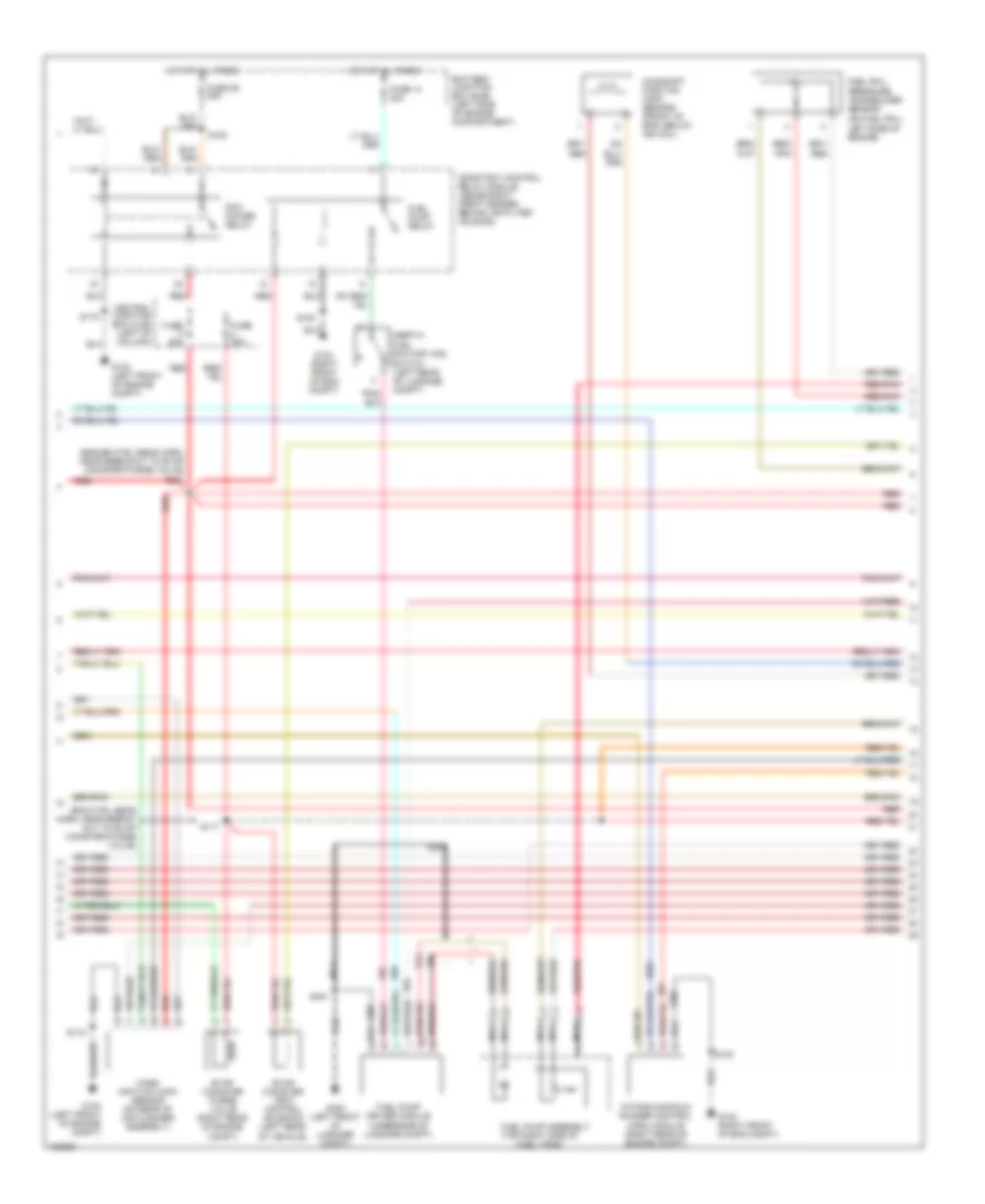
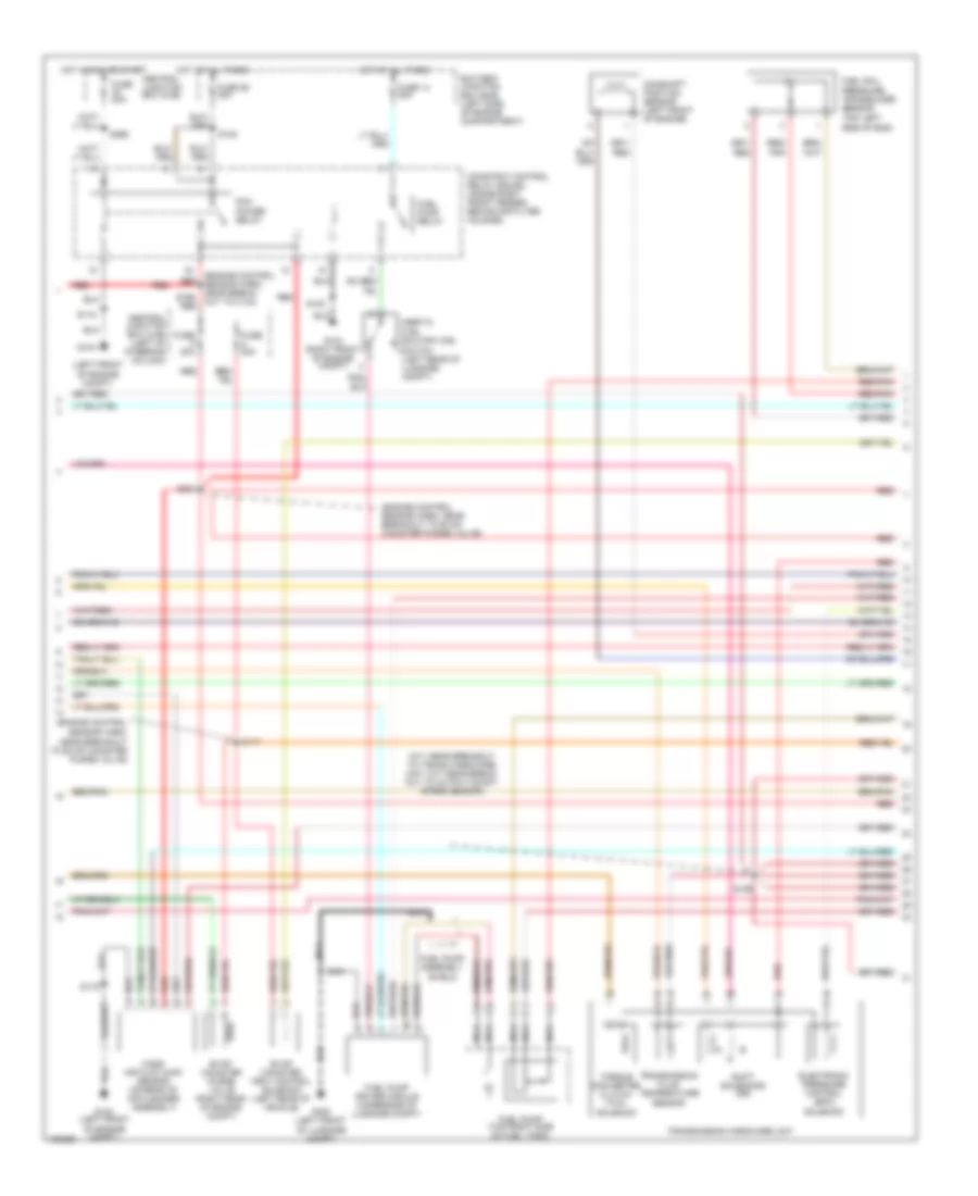
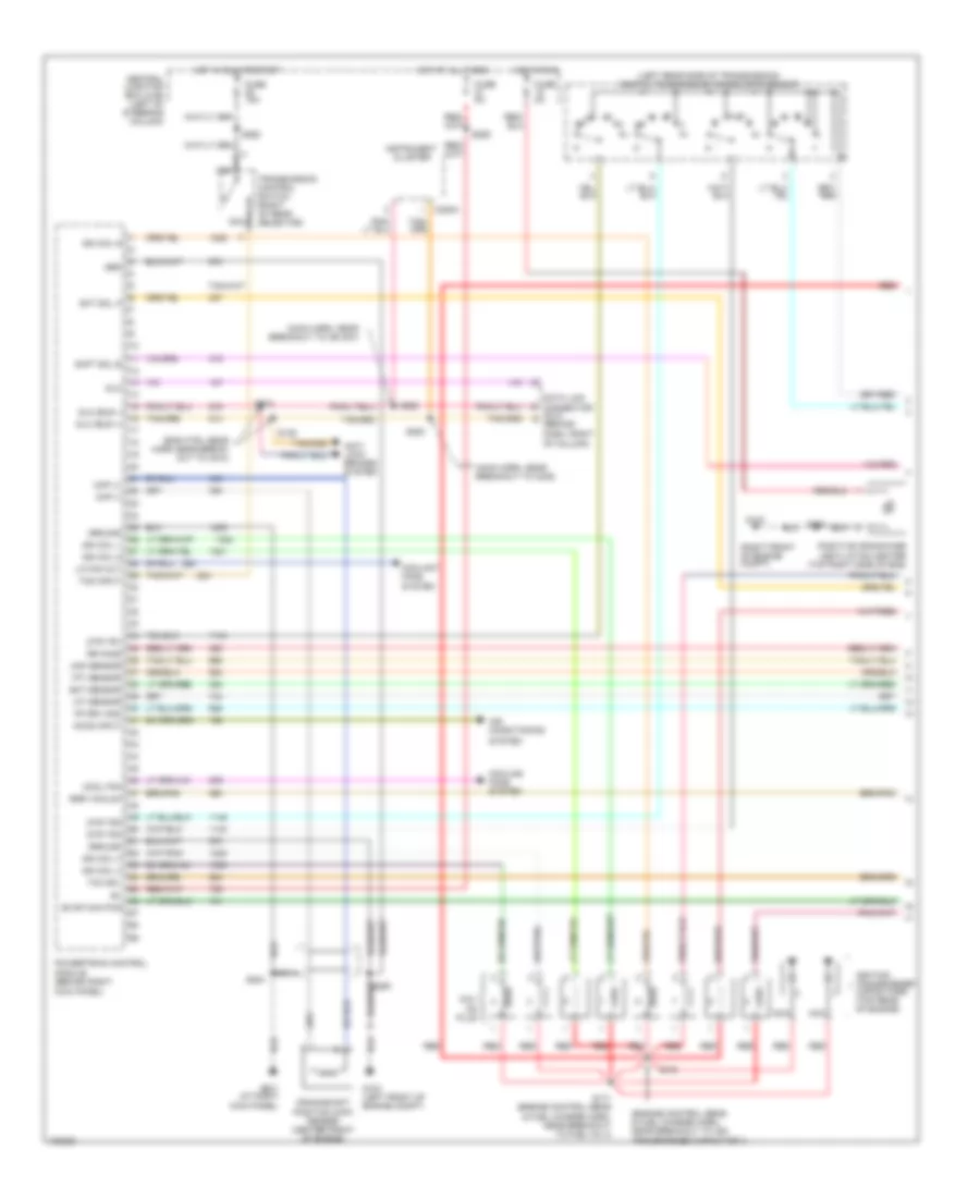
3.8L, Engine Performance Wiring Diagram (1 of 3) for Ford Mustang GT 2004

List of elements for 3.8L, Engine Performance Wiring Diagram (1 of 3) for Ford Mustang GT 2004:
- (a/t: near break- out to trans hard- ware unit, m/t: back-up lmp sw to rear lmp feed harn, near breakout to c1168)
- (eng ctrl sensor harn, near break- out to c210)
- (eng ctrl sensor harn, near breakout to c210)
- (main harn, near breakout to c238)
- (main harn, near breakout to ign switch)
- (on left rear side of transmission) digital transmission range (dtr) sensor
- A/c system
- Accs input
- Anti-lock brakes system
- C220a
- Central junction box (cjb) (left of column)
- Ckp (+)
- Ckp (-)
- Cooling fans system
- Crankshaft position sensor (center front of engine)
- Data link connector (dlc) (behind dash, right of column)
- Dlc
- Dlc (bus +)
- Dlc (bus -)
- Dtr tr1
- Dtr tr2
- Dtr tr4
- Egr vacuum
- Electronic pressure control (epc)
- Fp drv mod
- Fuse 15a
- Fuse 20a
- Fuse 5a
- G104 (left front of engine compt)
- G201 (right kick panel)
- Ground
- Hot at all times
- Hot in run or start
- Iat sensor
- Ign coil
- Ignition coil (rear left side of eng)
- Ignition transformer capacitor (rear of engine)
- Imrc ctrl
- Instrument cluster
- Low fan
- Maf sensor
- Module (behind right kick panel)
- Nca
- Powertrain control
- Red
- Rr ho2s
- S126
- S134
- S135
- S174
- S204
- S250
- S252
- S253
- S259
- S262
- Shft sol a
- Shft sol b
- Shift solenoids (ss)
- Solenoid
- Spark plugs
- Tcc sol
- Tcs input
- Tft sensor
- Torque converter clutch (tcc) solenoid
- Transmission control switch (right of gear selector)
- Transmission fluid temperature sensor
- Transmission hardware unit
- Vmv current
3.8L, Engine Performance Wiring Diagram (2 of 3) for Ford Mustang GT 2004
List of elements for 3.8L, Engine Performance Wiring Diagram (2 of 3) for Ford Mustang GT 2004:
- (eng ctrl sens harn, near break- out to evap canister purge valve)
- (engine ctrl sens harn, near breakout to evap canister purge valve) s234
- (top right side of fuel tank)
- Battery junction box (bjb) (left side of engine compartment)
- Camshaft position (cmp) sensor (front of eng, below ign coil)
- Central junction box (cjb) (left of column)
- Constant control relay module (inside right front fender, behind air filter housing)
- Evap canister purge valve (right rear of engine compt)
- Evap canister vent control solenoid (left rear of vehicle)
- Fuel pump assembly
- Fuel pump driver module (underside of luggage compt)
- Fuel pump relay
- Fuel rail pressure transducer sensor (on fuel rail, left side of engine)
- Fuse 14 20a
- Fuse 20a
- Fuse 26 30a
- G103 (right front of eng compt)
- G104 (left front of engine compt)
- G400 (left front of luggage compt)
- Hot at all times
- Inertia fuel shutoff (ifs) switch (left rear of luggage compt)
- Intake manifold runner control (imrc) module (right rear of engine compt)
- Mass air flow (maf) sensor (on rear of air cleaner assembly)
- Nca
- Pcm power relay
- Red
- Red/ pnk
- Red/pnk
- S100
- S108
- S115
- S117
- S451
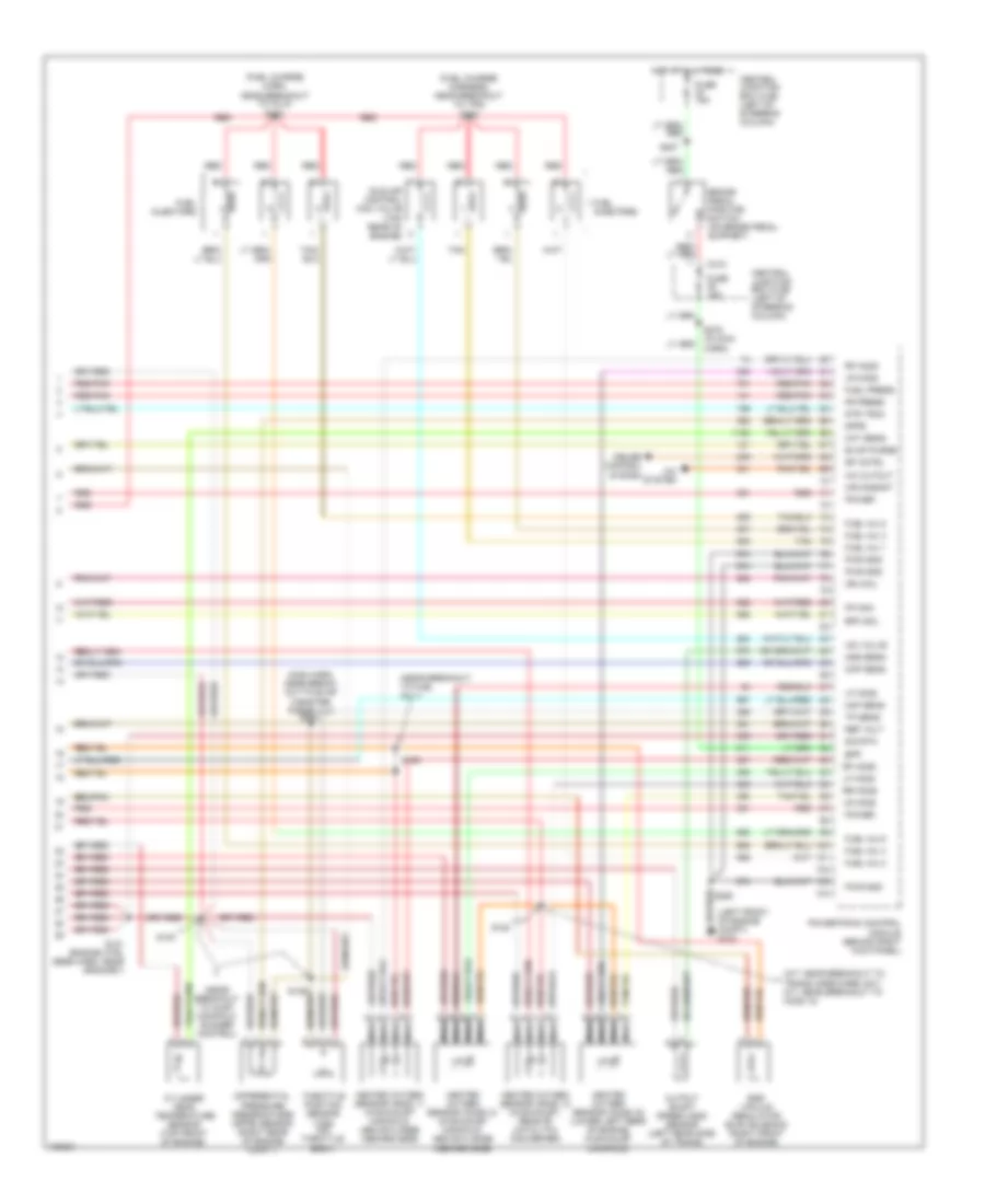
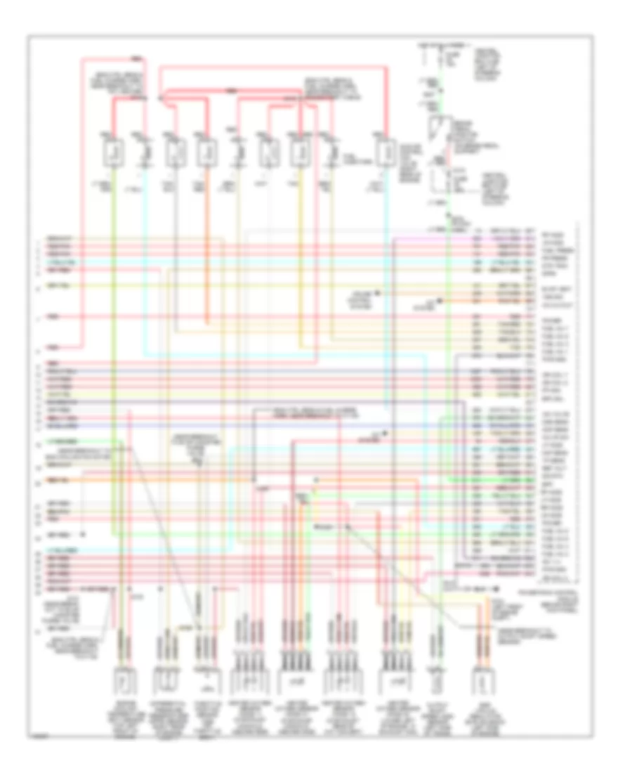
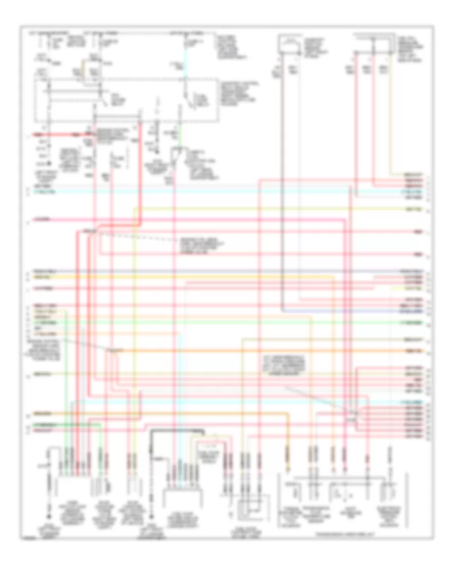
3.8L, Engine Performance Wiring Diagram (3 of 3) for Ford Mustang GT 2004
List of elements for 3.8L, Engine Performance Wiring Diagram (3 of 3) for Ford Mustang GT 2004:
- (a/t: near breakout to trans hardware unit, m/t: near breakout to ho2s 12)
- (fuel charge harn, near breakout to inj 6) s123
- (fuel charge harness, near breakout to tps) s128
- (left front of engine compt) g104
- (main harn, near break- out to evap canister purge vlv) s200
- (near breakout to fuel inj 1)
- (near breakout to inlet manifold runner control)
- A/c cutout
- A/c system
- Air mngmnt
- Bpp
- Brake pedal position switch (on brake pedal support)
- C315
- Central junction box (cjb) (left of steering column)
- Cht sens
- Cmp sens
- Cruise control system
- Cylinder head temperature sensor (top front of engine)
- Differential pressure feedback egr (dpfe) sensor (right rear of engine compt)
- Dpfe
- Dtr tr3a
- Egr vacuum regulator (evr) solenoid (right front of engine)
- Epc sol
- Evap purge
- Fp mon
- Fr press
- Fuel inj 1
- Fuel inj 2
- Fuel inj 3
- Fuel inj 4
- Fuel inj 5
- Fuel inj 6
- Fuel injectors
- Fuel press
- Fuse 15a
- Heated oxygen sensor (ho2s) 11 (in exhaust manifold, above flange inboard side)
- Heated oxygen sensor (ho2s) 12 (in exhaust, rear of catalytic converter)
- Heated oxygen sensor (ho2s) 21 (in exhaust manifold, above flange inboard side)
- Heated oxygen sensor (ho2s) 22 (lower left rear of engine, in exhaust manifold)
- Hot at all times
- Iac valve
- Idle air control (iac) valve (top rear of engine)
- Ign coil
- Lf ho2s
- Lr ho2s
- Maf sens
- Module (behind right kick panel)
- Nca
- Oss sens
- Output shaft speed (oss) sensor (left rear side of trans)
- Power
- Powertrain control
- Pwr gnd
- Red
- Red/pnk
- Ref volt
- Rf ho2s
- Rr ho2s
- S120
- S121 (engine ctrl sens harn, near grommet)
- S129
- S130
- S164
- S207
- S250
- S275 (in main harn)
- Sig rtn
- Sp cntrl
- Tan
- Throttle position sensor (tps) (on throttle body)
- Tp sens
3.9L
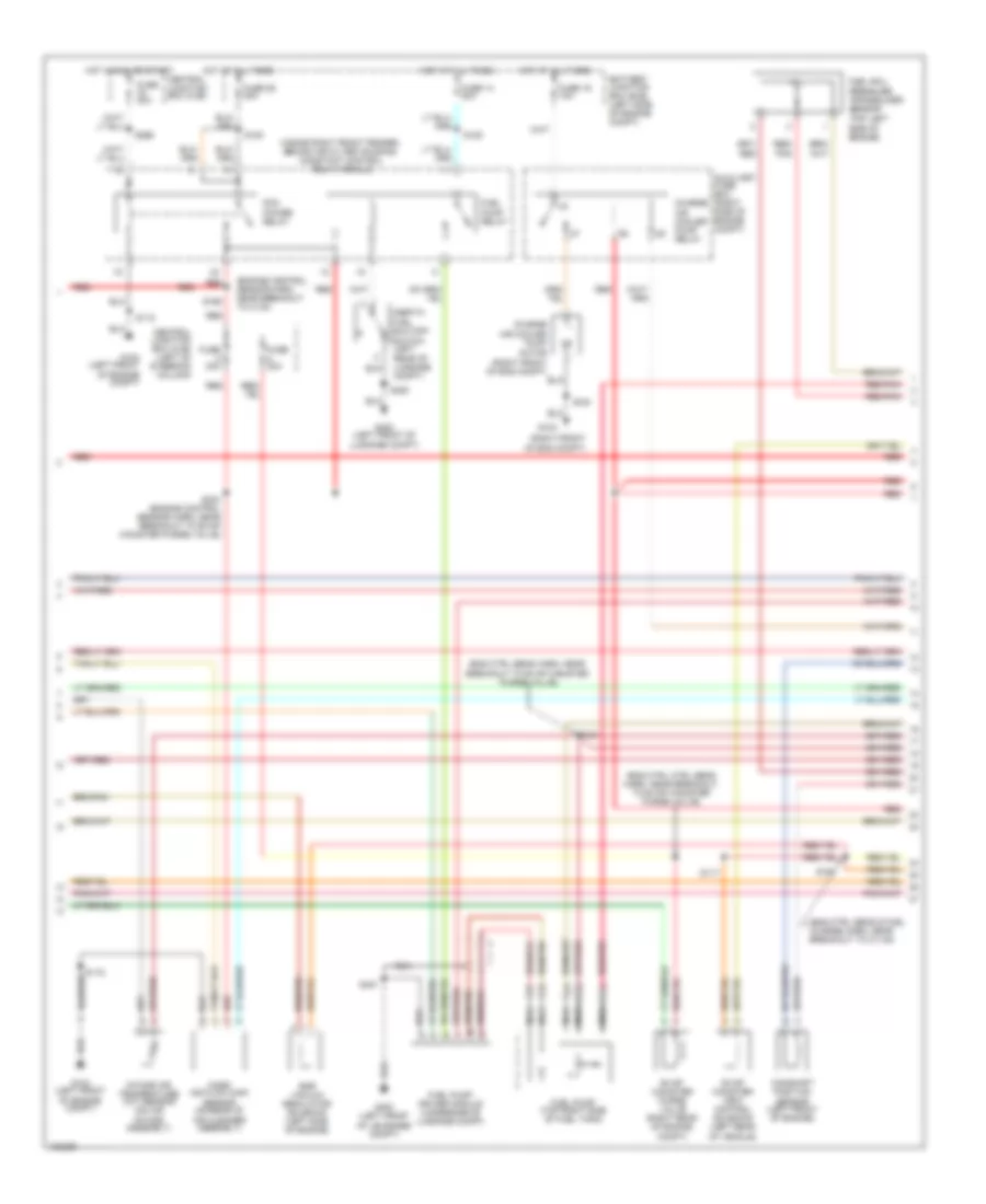
3.9L, Engine Performance Wiring Diagram (1 of 3) for Ford Mustang GT 2004
List of elements for 3.9L, Engine Performance Wiring Diagram (1 of 3) for Ford Mustang GT 2004:
- (a/t: near break- out to trans hard- ware unit, m/t: back-up lmp sw to rear lmp feed harn, near breakout to c1168)
- (eng ctrl sensor harn, near break- out to c210)
- (eng ctrl sensor harn, near breakout to c210)
- (main harn, near breakout to c238)
- (main harn, near breakout to ign switch)
- (on left rear side of transmission) digital transmission range (dtr) sensor
- A/c system
- Accs input
- Anti-lock brakes system
- C220a
- Central junction box (cjb) (left of column)
- Ckp (+)
- Ckp (-)
- Cooling fans system
- Crankshaft position sensor (center front of engine)
- Data link connector (dlc) (behind dash, right of column)
- Dlc
- Dlc (bus +)
- Dlc (bus -)
- Dtr tr1
- Dtr tr2
- Dtr tr4
- Egr vacuum
- Electronic pressure control (epc)
- Fp drv mod
- Fuse 15a
- Fuse 20a
- Fuse 5a
- G104 (left front of engine compt)
- G201 (right kick panel)
- Ground
- Hot at all times
- Hot in run or start
- Iat sensor
- Ign coil
- Ignition coil (rear left side of eng)
- Ignition transformer capacitor (rear of engine)
- Imrc ctrl
- Instrument cluster
- Low fan
- Maf sensor
- Module (behind right kick panel)
- Nca
- Powertrain control
- Red
- Rr ho2s
- S126
- S134
- S135
- S174
- S204
- S250
- S252
- S253
- S259
- S262
- Shft sol a
- Shft sol b
- Shift solenoids (ss)
- Solenoid
- Spark plugs
- Tcc sol
- Tcs input
- Tft sensor
- Torque converter clutch (tcc) solenoid
- Transmission control switch (right of gear selector)
- Transmission fluid temperature sensor
- Transmission hardware unit
- Vmv current
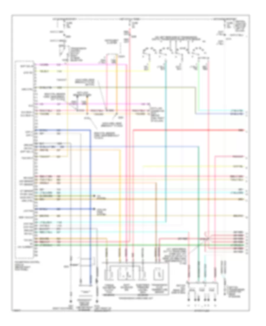
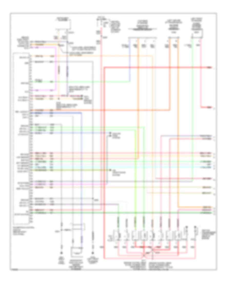
3.9L, Engine Performance Wiring Diagram (2 of 3) for Ford Mustang GT 2004
List of elements for 3.9L, Engine Performance Wiring Diagram (2 of 3) for Ford Mustang GT 2004:
- (eng ctrl sens harn, near break- out to evap canister purge valve)
- (engine ctrl sens harn, near breakout to evap canister purge valve) s234
- (top right side of fuel tank)
- Battery junction box (bjb) (left side of engine compartment)
- Camshaft position (cmp) sensor (front of eng, below ign coil)
- Central junction box (cjb) (left of column)
- Constant control relay module (inside right front fender, behind air filter housing)
- Evap canister purge valve (right rear of engine compt)
- Evap canister vent control solenoid (left rear of vehicle)
- Fuel pump assembly
- Fuel pump driver module (underside of luggage compt)
- Fuel pump relay
- Fuel rail pressure transducer sensor (on fuel rail, left side of engine)
- Fuse 14 20a
- Fuse 20a
- Fuse 26 30a
- G103 (right front of eng compt)
- G104 (left front of engine compt)
- G400 (left front of luggage compt)
- Hot at all times
- Inertia fuel shutoff (ifs) switch (left rear of luggage compt)
- Intake manifold runner control (imrc) module (right rear of engine compt)
- Mass air flow (maf) sensor (on rear of air cleaner assembly)
- Nca
- Pcm power relay
- Red
- Red/ pnk
- Red/pnk
- S100
- S108
- S115
- S117
- S451
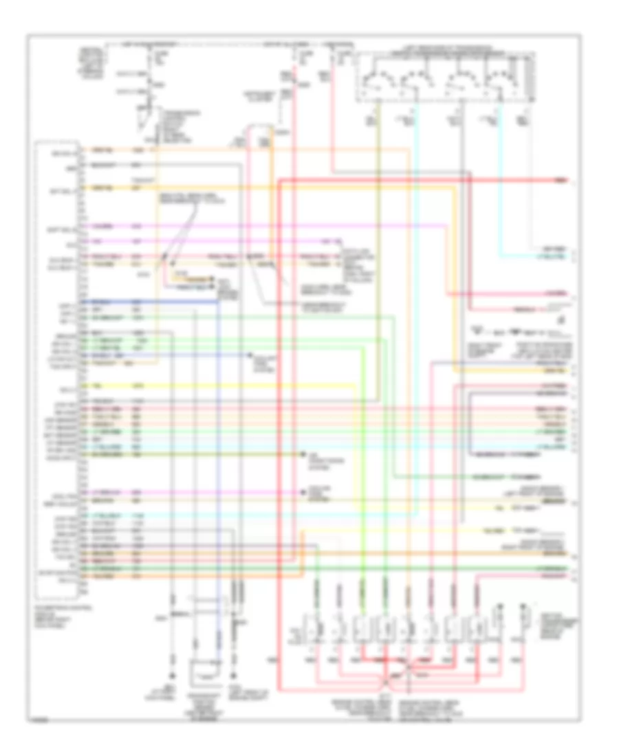
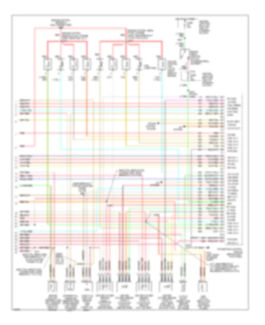
3.9L, Engine Performance Wiring Diagram (3 of 3) for Ford Mustang GT 2004
List of elements for 3.9L, Engine Performance Wiring Diagram (3 of 3) for Ford Mustang GT 2004:
- (a/t: near breakout to trans hardware unit, m/t: near breakout to ho2s 12)
- (fuel charge harn, near breakout to inj 6) s123
- (fuel charge harness, near breakout to tps) s128
- (left front of engine compt) g104
- (main harn, near break- out to evap canister purge vlv) s200
- (near breakout to fuel inj 1)
- (near breakout to inlet manifold runner control)
- A/c cutout
- A/c system
- Air mngmnt
- Bpp
- Brake pedal position switch (on brake pedal support)
- C315
- Central junction box (cjb) (left of steering column)
- Cht sens
- Cmp sens
- Cruise control system
- Cylinder head temperature sensor (top front of engine)
- Differential pressure feedback egr (dpfe) sensor (right rear of engine compt)
- Dpfe
- Dtr tr3a
- Egr vacuum regulator (evr) solenoid (right front of engine)
- Epc sol
- Evap purge
- Fp mon
- Fr press
- Fuel inj 1
- Fuel inj 2
- Fuel inj 3
- Fuel inj 4
- Fuel inj 5
- Fuel inj 6
- Fuel injectors
- Fuel press
- Fuse 15a
- Heated oxygen sensor (ho2s) 11 (in exhaust manifold, above flange inboard side)
- Heated oxygen sensor (ho2s) 12 (in exhaust, rear of catalytic converter)
- Heated oxygen sensor (ho2s) 21 (in exhaust manifold, above flange inboard side)
- Heated oxygen sensor (ho2s) 22 (lower left rear of engine, in exhaust manifold)
- Hot at all times
- Iac valve
- Idle air control (iac) valve (top rear of engine)
- Ign coil
- Lf ho2s
- Lr ho2s
- Maf sens
- Module (behind right kick panel)
- Nca
- Oss sens
- Output shaft speed (oss) sensor (left rear side of trans)
- Power
- Powertrain control
- Pwr gnd
- Red
- Red/pnk
- Ref volt
- Rf ho2s
- Rr ho2s
- S120
- S121 (engine ctrl sens harn, near grommet)
- S129
- S130
- S164
- S207
- S250
- S275 (in main harn)
- Sig rtn
- Sp cntrl
- Tan
- Throttle position sensor (tps) (on throttle body)
- Tp sens
4.6L DOHC
4.6L DOHC, Engine Performance Wiring Diagram (1 of 3) for Ford Mustang GT 2004
List of elements for 4.6L DOHC, Engine Performance Wiring Diagram (1 of 3) for Ford Mustang GT 2004:
- (eng ctrl sens harn, near breakout to c210)
- (engine control sens & fuel charge harn, near breakout to idle air control valve)
- (left rear side of transmission) digital transmission range (dtr) sensor
- (main harn, near breakout to c238)
- (near breakout to ignition sw)
- (right front of engine compt)
- Accs input
- Air conditioning
- Anti- lock brakes system
- C220a
- Central junction box (cjb) (left of steering column)
- Ckp (+)
- Ckp (-)
- Coil on plug
- Cool fan
- Coolant fans system
- Cooling fans system
- Crankshaft position sensor (center front of engine)
- Data link connector (dlc) (behind dash, right of column)
- Dlc
- Dlc (bus +)
- Dlc (bus -)
- Dtr tr1
- Dtr tr2
- Dtr tr4
- Ect sensor
- Egr vacuum
- Evap can pur
- Fp drv mod
- Fuse 15a
- Fuse 2a
- Fuse 5a
- G103
- G104 (left front of engine compt)
- G201 (at right kick panel)
- Grd
- Ground
- Hot at all times
- Hot in run
- Hot in run or start
- Iat sensor
- Ign coil 1
- Ign coil 3
- Ign coil 4
- Ign coil 5
- Ign coil 6
- Ignition transformer capacitors (rear of engine)
- Instrument cluster
- Knock sensor 1 (left front of engine)
- Knock sensor 2 (right front of engine)
- Ks 1 (-)
- Ks 2 (+)
- Ks 2 (-)
- Lo fan out
- Maf sensor
- Module (behind right kick panel)
- Nca
- Positive crankcase ventilation heater (top left rear of eng)
- Powertrain control
- Red
- Rr ho2s
- S134
- S135
- S170
- S171 (engine control sens & fuel charge harn, near breakout to c1148)
- S204
- S250
- S252
- S253
- S259
- S262
- Shft sol b
- Sht sol a
- System
- Tcc sol
- Tcs input
- Tft sensor
- Transmission control switch (right of gear selector)
4.6L DOHC, Engine Performance Wiring Diagram (2 of 3) for Ford Mustang GT 2004
List of elements for 4.6L DOHC, Engine Performance Wiring Diagram (2 of 3) for Ford Mustang GT 2004:
- (a/t: near breakout to trans hardware unit, m/t: near break- out to output shaft speed sensor)
- (engine control sensor harn, near break- out to c133) red
- (engine control sensor harn, near breakout to evap canister purge valve)
- (left front of engine compt)
- Battery junction box (bjb) (left side of engine compartment)
- Camshaft position sensor (left front of engine)
- Central junction box (cjb)
- Central junction box (cjb) (left of steering column)
- Constant control relay moduel (inside right front fender, behind air filter housing)
- Electronic pressure control (epc)
- Evap canister purge valve (right rear of engine compt)
- Evap canister vent control solenoid (left rear of vehicle)
- Fuel pump (top right side of fuel tank)
- Fuel pump assembly shield
- Fuel pump driver module (underside of luggage compt)
- Fuel pump relay
- Fuel rail pressure transducer sensor (top left side of eng)
- Fuse 14 20a
- Fuse 20a
- Fuse 26 30a
- G103 (right front of engine compt)
- G104
- G104 (left front of engine compt)
- G400 (left front
- Hot at all times
- Hot in run or start
- Inertia fuel shutoff (ifs) switch (left rear of luggage compt)
- Mass air flow (maf) sensor (on rear of air cleaner assembly)
- Nca
- Of luggage compt)
- Pcm power relay
- Red
- Red/ pnk
- Red/pnk
- S100
- S108
- S115
- S117
- S126
- S169
- S234
- S266
- S451
- Shift solenoids (ss)
- Solenoid
- Torque converter clutch (tcc) solenoid
- Transmission fluid temperature sensor
- Transmission hardware unit
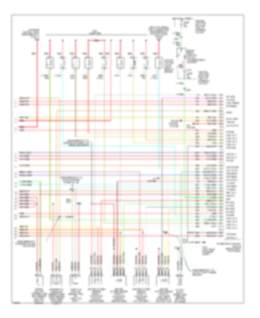
4.6L DOHC, Engine Performance Wiring Diagram (3 of 3) for Ford Mustang GT 2004
List of elements for 4.6L DOHC, Engine Performance Wiring Diagram (3 of 3) for Ford Mustang GT 2004:
- (eng ctrl sens & fuel charge harn, near breakout to c1148)
- (eng ctrl sens & fuel charge harn, near breakout to pcv heater) s148
- (eng ctrl sens & fuel charge harn, near breakout to pos battery cable)
- (near breakout to eng cooling fan motor)
- (near breakout to evap canister purge valve)
- (near breakout to output shaft speed sensor)
- A/c cutout
- A/c hp sw
- A/c system
- Bpp
- Brake pedal position switch (on brake pedal support)
- C315
- Central junction box (cjb) (left of steering column)
- Cmp sens
- Cruise control system
- Differential pressure feedback egr (dpfe) sensor (right rear of engine compt)
- Dpfe
- Dtr tr3a
- Egr vacuum regulator (evr) solenoid (left side of engine)
- Engine coolant temperature (ect) sensor (top left front of engine)
- Epc sol
- Evap vent
- Fp mon
- Fr press
- Fuel inj 1
- Fuel inj 2
- Fuel inj 3
- Fuel inj 4
- Fuel inj 5
- Fuel inj 6
- Fuel inj 7
- Fuel inj 8
- Fuel injectors
- Fuel press
- Fuse 15a
- G104 (left front of engine compt)
- Heated oxygen sensor (ho2s) 11 (in exhaust manifold, inboard side)
- Heated oxygen sensor (ho2s) 12 (in exhaust, rear of cat convert)
- Heated oxygen sensor (ho2s) 21 (in exhaust manifold, inboard side)
- Heated oxygen sensor (ho2s) 22 (lower left of engine, in exhaust man)
- Hot at all times
- Iac valve
- Idle air control (iac) valve (right rear of engine)
- Ign coil 2
- Ign coil 7
- Ign coil 8
- Ks 1 (+)
- Lf ho2s
- Lr ho2s
- Maf sens
- Module (behind right kick panel)
- Nca
- Oss sens
- Output shaft speed (oss) sensor (left side of trans)
- Power
- Powertrain control
- Pwr gnd
- Red
- Red/pnk
- Ref volt
- Rf ho2s
- Rr ho2s
- S115
- S120
- S121 (near break- out to evap canister purge valve)
- S129
- S130
- S147
- S164
- S200
- S207
- S275 (in main harn)
- Sig rtn
- Tan
- Tan/ red
- Tan/red
- Throttle position sensor (tps) (on throttle body)
- Tp sens
- Vss sig
4.6L SC
4.6L SC, Engine Performance Wiring Diagram (1 of 3) for Ford Mustang GT 2004
List of elements for 4.6L SC, Engine Performance Wiring Diagram (1 of 3) for Ford Mustang GT 2004:
- (behind dash, right of column)
- (eng ctrl sens harn, near breakout to c210)
- (engine control sens & fuel charge harn, near breakout to idle air control valve)
- (left center of transmission)
- (left front of engine)
- (main harn, near break- out to c238)
- (main harn, near break- out to ignition switch)
- (top rear of engine)
- Accs input
- Air conditioning
- Anti- lock brakes system
- Bap sig
- Barometric absolute pressure sensor
- C220a
- Central junction box (cjb) (left of steering column)
- Ckp (+)
- Ckp (-)
- Coil on plug
- Cool fan
- Cooling fans system
- Crankshaft position (ckp) sensor (center front of engine)
- Data link connector (dlc)
- Dlc
- Dlc (bus +)
- Dlc (bus -)
- Ect sensor
- Egr vacuum
- Evap can pur
- Fp drv mod
- Fuse 5a
- G104 (left front of engine compt)
- G201 (right kick panel)
- Grd
- Ground
- Hot at all times
- Iat sensor
- Ign coil 1
- Ign coil 3
- Ign coil 4
- Ign coil 5
- Ign coil 6
- Ignition transformer capacitors (rear of engine)
- Instrument cluster
- Lo fan out
- Maf sensor
- Module (behind right kick panel)
- Nca
- Powertrain control
- Red
- Rev lockout
- Reverse lockout solenoid
- Rr ho2s
- S134
- S135 (eng ctrl sens harn, near breakout to c210)
- S170
- S171 (engine control sens & fuel charge harn, near breakout to fuel inj 4)
- S204
- S250
- S252
- S253
- S259
- Sc bypass
- Super- charger by-pass solenoid
- System
- Tan/ red
- Tan/red
4.6L SC, Engine Performance Wiring Diagram (2 of 3) for Ford Mustang GT 2004
List of elements for 4.6L SC, Engine Performance Wiring Diagram (2 of 3) for Ford Mustang GT 2004:
- (eng ctrl ctrl sens harn, near breakout to evap canister purge valve)
- (eng ctrl sens & fuel charge harn, near breakout to c1148)
- (eng ctrl sens harn, near breakout to evap canister purge valve)
- (engine control sensor harn, near breakout to c133)
- (inside right front fender, behind air filter housing) constant control relay module
- (right front of eng compt)
- Auxiliary fuse box (right side of engine compt)
- Battery junction box (bjb) (left side of engine compt)
- Camshaft position sensor (left front of engine)
- Central junction box (cjb)
- Central junction box (cjb) (left of steering column)
- Charge air cooler pump motor (right front of eng compt)
- Charge air cooler pump relay
- Egr vacuum regulator solenoid (left side of engine)
- Evap canister purge valve (right rear of engine compt)
- Evap canister vent control solenoid (left rear of vehicle)
- Fuel pump (top right side of fuel tank)
- Fuel pump driver module (underside of luggage compt)
- Fuel pump relay
- Fuel rail pressure transducer sensor (top left side of engine)
- Fuse 14 20a
- Fuse 19 10a
- Fuse 20a
- Fuse 26 30a
- G103
- G104 (left front of engine compt)
- G400 (left front
- G400 (left front of luggage compt)
- Hot at all times
- Hot in run or start
- Inertia fuel shutoff switch (left rear of luggage compt)
- Intake air temperature (iat) sensor (on air intake assembly)
- Mass air flow (maf) sensor (on rear of air cleaner assembly)
- Nca
- Of leuggage compt)
- Pcm power relay
- Red
- Red/ pnk
- Red/pnk
- S100
- S108
- S115
- S117
- S121
- S125
- S164
- S169
- S234 (engine control sensor harn, near breakout to evap canister purge valve)
- S266
- S450
- S451
4.6L SC, Engine Performance Wiring Diagram (3 of 3) for Ford Mustang GT 2004
List of elements for 4.6L SC, Engine Performance Wiring Diagram (3 of 3) for Ford Mustang GT 2004:
- (eng ctrl sens & fuel charge harn, near breakout to positive bat cable) s147
- (in engine control harn, near breakout to inj 7) s148
- (near breakout to barometric absolute pressure sensor
- (near breakout to engine cooling fan motor)
- (near breakout to evap canister purge valve)
- (near breakout to output shaft speed sensor)
- A/c cutout
- A/c hp sw
- A/c system
- Air cooler
- Bpp
- Brake pedal position switch (on brake pedal support)
- C315
- Central junction box (cjb) (left of steering column)
- Cmp sens
- Cruise control system
- Differential pressure feedback egr (dpfe) sensor (right rear of engine compt)
- Dpfe
- Engine coolant temperature (ect) sensor (top left front of engine)
- Evap vent
- Fp mon
- Fr press
- Fuel inj 1
- Fuel inj 2
- Fuel inj 3
- Fuel inj 4
- Fuel inj 5
- Fuel inj 6
- Fuel inj 7
- Fuel inj 8
- Fuel injectors
- Fuel press
- Fuse 15a
- G104 (left front of engine compt)
- Heated oxygen sensor (ho2s) 11 (in exhaust manifold, inboard side)
- Heated oxygen sensor (ho2s) 12 (in exhaust, rear of cat convert)
- Heated oxygen sensor (ho2s) 21 (in exhaust manifold, inboard side)
- Heated oxygen sensor (ho2s) 22 (left rear of engine, in exhaust man)
- Hot at all times
- Iac valve
- Idle air control valve (right rear of engine)
- Ign coil 2
- Ign coil 7
- Ign coil 8
- Lf ho2s
- Lr ho2s
- Maf sens
- Module (behind right kick panel)
- Nca
- Oss sens
- Output shaft speed (oss) sensor (left side of trans)
- Power
- Powertrain control
- Pwr gnd
- Red
- Red/pnk
- Ref volt
- Rf ho2s
- Rr ho2s
- S115
- S120
- S126
- S129
- S130
- S200
- S207
- S275
- Sig rtn
- Tan
- Tan/ red
- Tan/red
- Throttle position sensor (tps) (on throttle body)
- Tp sens
- Vss sig
4.6L SOHC
4.6L SOHC, Engine Performance Wiring Diagram (1 of 3) for Ford Mustang GT 2004
List of elements for 4.6L SOHC, Engine Performance Wiring Diagram (1 of 3) for Ford Mustang GT 2004:
- (eng ctrl sens harn near break- out to c210)
- (engine control sens & fuel charge harn, near breakout to ign transformer capacitor 1)
- (left rear side of transmission) digital transmission range (dtr) sensor
- (main harn, near breakout to c238)
- (main harn, near breakout to ign sw)
- (right front of engine compt)
- Accs input
- Air conditioning
- Anti- lock brakes system
- C220a
- Central junction box (cjb) (left of steering column)
- Ckp (+)
- Ckp (-)
- Coil on plug
- Cool fan
- Coolant fans system
- Cooling fans system
- Crankshaft position (ckp) sensor (center front of engine)
- Data link connector (dlc) (behind dash, right of column)
- Dlc
- Dlc (bus +)
- Dlc (bus -)
- Dtr tr1
- Dtr tr2
- Dtr tr4
- Ect sensor
- Egr vacuum
- Evap can pur
- Fp drv mod
- Fuse 15a
- Fuse 2a
- Fuse 5a
- G103
- G104 (left front of engine compt)
- G201 (at right kick panel)
- Grd
- Ground
- Hot at all times
- Hot in run
- Hot in run or start
- Iat sensor
- Ign coil 1
- Ign coil 3
- Ign coil 4
- Ign coil 5
- Ign coil 6
- Ignition transformer capacitors (top rear of engine)
- Instrument cluster
- Lo fan out
- Maf sensor
- Module (behind right kick panel)
- Nca
- Positive crankcase ventilation heater (top right side of eng)
- Powertrain control
- Red
- Rr ho2s
- S134
- S135
- S170
- S171 (engine control sens & fuel charge harn, near breakout to fuel inj 4)
- S204
- S250
- S252
- S253
- S259
- S262
- Shft sol b
- Sht sol a
- System
- Tcc sol
- Tcs input
- Tft sensor
- Transmission control switch (right of gear selector)
4.6L SOHC, Engine Performance Wiring Diagram (2 of 3) for Ford Mustang GT 2004
List of elements for 4.6L SOHC, Engine Performance Wiring Diagram (2 of 3) for Ford Mustang GT 2004:
- (a/t: near breakout to trans hardware unit, m/t: nearbreak- out to output shaft speed sensor)
- (engine control sensor harn, near breakout to c133) red
- (engine control sensor harn, near breakout to evap canister purge valve)
- (engine ctrl sens harn, near breakout to evap canister purge valve)
- (left front of engine compt)
- Battery junction box (bjb) (left side of engine compartment)
- Camshaft position sensor (left front of eng)
- Central junction box (cjb)
- Central junction box (cjb) (left of steering column)
- Constant control relay module (inside right front fender, behind air filter housing)
- Electronic pressure control (epc)
- Evap canister purge valve (right rear of engine compt)
- Evap canister vent control solenoid (left rear of vehicle)
- Fuel pump (top right side of fuel tank)
- Fuel pump assembly shield
- Fuel pump driver module (underside of luggage compt)
- Fuel pump relay
- Fuel rail pressure transducer sensor (top left side of eng)
- Fuse 14 20a
- Fuse 20a
- Fuse 26 30a
- G103 (right front of engine compt)
- G104
- G104 (left front of engine compt)
- G400 (left front
- Hot at all times
- Hot in run or start
- Inertia fuel shutoff (ifs) switch (left rear of luggage compartment)
- Mass air flow (maf) sensor (on rear of air cleaner assembly)
- Nca
- Of luggage compartment)
- Pcm power relay
- Red
- Red/ pnk
- Red/pnk
- S100
- S108
- S115
- S117
- S126
- S169
- S234
- S266
- S451
- Shift solenoids (ss)
- Solenoid
- Torque converter clutch (tcc) solenoid
- Transmission fluid temperature sensor
- Transmission hardware unit
4.6L SOHC, Engine Performance Wiring Diagram (3 of 3) for Ford Mustang GT 2004
List of elements for 4.6L SOHC, Engine Performance Wiring Diagram (3 of 3) for Ford Mustang GT 2004:
- (a/t: near breakout to trans hardware unit, m/t: near breakout to reversing lamps switch)
- (eng ctrl sens & fuel charge harn, near breakout to c1148)
- (eng ctrl sens harn, near breakout to evap canister purge valve)
- (engine control sens & fuel charge harn, near breakout to coil on plug 2) s128
- (engine control sensor & fuel charge harn) s158
- (engine control sensor & fuel charge harn, near fuel inj 7) s123
- (near break- out to coil on plug 3)
- (near breakout to evap canister purge valve)
- A/c cutout
- A/c hp sw
- A/c system
- Bpp
- Brake pedal position switch (on brake pedal support)
- C315
- Central junction box (cjb) (left of steering column)
- Cmp sens
- Cruise control system
- Differential pressure feedback egr (dpfe) sensor (left rear of engine compt)
- Dpfe
- Dtr tr3a
- Egr vacuum regulator solenoid (left rear of eng)
- Engine coolant temperature (ect) sensor (top right front of engine)
- Epc sol
- Evap vent
- Fp mon
- Fr press
- Fuel inj 1
- Fuel inj 2
- Fuel inj 3
- Fuel inj 4
- Fuel inj 5
- Fuel inj 6
- Fuel inj 7
- Fuel inj 8
- Fuel injectors
- Fuel press
- Fuse 15a
- G104 (left front of engine compt)
- Heated oxygen sensor (ho2s) 11 (in exhaust manifold, inboard side)
- Heated oxygen sensor (ho2s) 12 (in exhaust, rear of cat convert)
- Heated oxygen sensor (ho2s) 21 (in exhaust manifold, inboard side)
- Heated oxygen sensor (ho2s) 22 (left rear of engine, in exhaust man)
- Hot at all times
- Iac valve
- Idle air control (iac) valve (right rear of engine)
- Ign coil 2
- Ign coil 7
- Ign coil 8
- Lf ho2s
- Lr ho2s
- Maf sens
- Module (behind right kick panel)
- Nca
- Oss sens
- Output shaft speed (oss) sensor (left side of trans)
- Power
- Powertrain control
- Pwr gnd
- Red
- Red/pnk
- Ref volt
- Rf ho2s
- Rr ho2s
- S115
- S120
- S121
- S129
- S164
- S200
- S207
- S275 (in main harn)
- Sig rtn
- Tan
- Tan/ red
- Tan/red
- Throttle position sensor (tps) (on throttle body)
- Tp sens
- Vss sig