DEFOGGERS
Defogger Wiring Diagram for Nissan Maxima GXE 1997
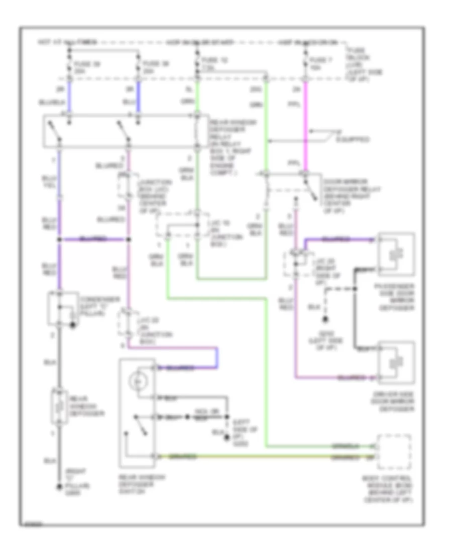
List of elements for Defogger Wiring Diagram for Nissan Maxima GXE 1997:
- (left side of i/p) g202
- (right "c" pillar) g905
- 20g
- Body control module (bcm) (behind left center of i/p)
- Condenser (left "c" pillar)
- Door mirror defogger relay (behind right center of i/p)
- Driver side door mirror defogger
- Fuse 12 7.5a
- Fuse 38 20a
- Fuse 39 20a
- Fuse 7 10a
- Fuse block (j/b) (left side of i/p)
- G202 (left side of i/p)
- Hot at all times
- Hot in acc or on
- Hot in on or start
- If equipped
- J/c 10 (in junction box)
- J/c 20 (right side of i/p)
- J/c 22 (in junction box)
- Junction box (j/c) (behind center of i/p)
- Passenger side door mirror defogger
- Rear window defogger
- Rear window defogger relay (in relay box 1, right side of engine compt.)
- Rear window defogger switch
 Čeština
 Dansk
Dansk Deutsch
 Ελληνικά
 English
 English
 Español
 Suomi
Suomi Français
 Français
 עברית
עברית Hrvatski
 Italiano
 日本語
日本語 한국어
한국어 Nederlands
 Polski
 Português
 Português
 Română
 Русский
 Slovenčina
 Slovenščina
 Svenska
 Türkçe
 中文 (中国)
 Magyar