
 Čeština
 Dansk
Dansk Deutsch
 Ελληνικά
 English
 English
 Español
 Suomi
Suomi Français
 Français
 עברית
עברית Hrvatski
 Magyar
 Italiano
 日本語
日本語 한국어
한국어 Nederlands
 Polski
 Português
 Română
 Русский
 Slovenčina
 Slovenščina
 Svenska
 Türkçe
 中文 (中国)

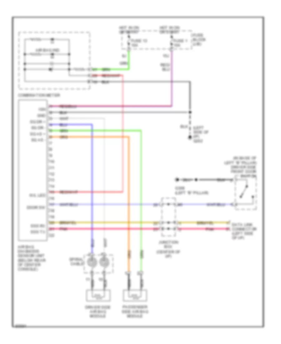
SUPPLEMENTAL RESTRAINTS
Supplemental Restraint Wiring Diagram for Nissan Maxima GXE 1997
List of elements for Supplemental Restraint Wiring Diagram for Nissan Maxima GXE 1997:

BODY COMPUTERAIR CONDITIONINGCOMPUTER DATA LINESANTI-LOCK BRAKESCRUISE CONTROLCOOLING FANANTI-THEFTEXTERIOR LIGHTSGROUND DISTRIBUTIONHEADLIGHTSDEFOGGERSINSTRUMENT CLUSTERPOWER DOOR LOCKSENGINE PERFORMANCEHORNPOWER ANTENNAINTERIOR LIGHTSPOWER MIRRORSRADIOPOWER DISTRIBUTIONPOWER WINDOWSPOWER SEATSSHIFT INTERLOCKSSTARTING/CHARGINGSUPPLEMENTAL RESTRAINTSPOWER TOP/SUNROOFTRANSMISSIONWARNING SYSTEMSWIPER/WASHERTRUNK, TAILGATE, FUEL DOOR