СИСТЕМА КОНДИЦИОНЕРА
Электросхема кондиционера, Основная (1 из 2) для Audi A4 2.0T Quattro 2011

Электросхема кондиционера, Основная (1 из 2) для Audi A4 2.0T Quattro 2011 - Список элементов:
- (left side of center tunnel) g687
- 10a
- 12a
- 3.0l
- A/c compressor regulator valve (rear of a/c compressor)
- A/c pressure/ temperature sensor (left side of condenser)
- Air flow door motor (left side of air intake housing)
- Brake light switch
- Center outlet temperature sensor
- Center vent adjustment motor
- Climatronic control module
- Computer data lines system
- Coolant pump (if equipped)
- Defroster door motor (left side of a/c unit)
- Driver's side fuse panel (behind left end of dash)
- Engine coolant level (ecl) sensor
- Evaporator vent temperature sensor (in evaporator housing)
- Footwell flap motor
- Footwell outlet temperature sensor
- Fuse 10a
- Fuse 40a
- Fuse 5a
- Fuse carrier
- G638 (behind right kick panel)
- G639 (behind left kick panel)
- Hot at all times
- Outside air temperature sensor (behind front grille)
- Passenger's side fuse panel (behind right end of dash)
- Recirculation door motor (left side of air intake housing)
- Red
- Sunlight photo sensor (under center of dash)
- T16b
- T16i
- T17b
- T17i
- T17ir
- T17q
- T20e
- T32b
- Temperature regulator flap motor
- Vehicle electrical system control module (under left side of dash)
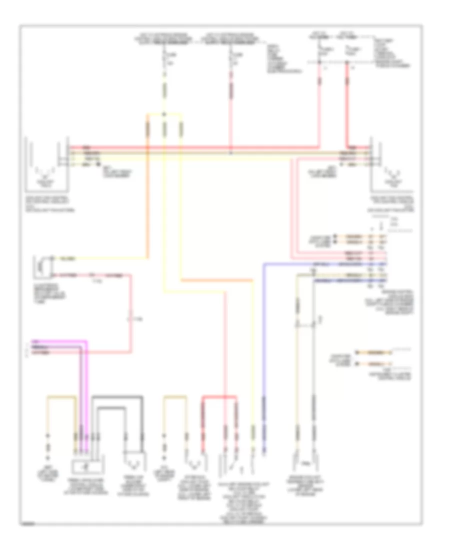
Электросхема кондиционера, Основная (2 из 2) для Audi A4 2.0T Quattro 2011
Электросхема кондиционера, Основная (2 из 2) для Audi A4 2.0T Quattro 2011 - Список элементов:
- 11a
- 2.ol
- 3.0l
- After run coolant pump (2.0l: lower left side of engine) (3.0l: lower left front of engine)
- Auxiliary engine coolant (ec) pump relay (3.0l w/ 8z9) coolant circulation (ec) pump relay (2.0l w/ after run coolant pump) (2.0l w/ after run coolant pump: on e-box relay/fuse carrier)
- Battery jump start terminal (middle of engine compt plenum chamber)
- Climatronic refrigerant shut-off valve (on refrigerant tube)
- Computer data lines system
- Coolant fan
- Coolant fan 2
- Coolant fan control (fc) control module (3.0l) (on coolant fan motor)
- Coolant fan control (fc) control module 2 (3.0l) (on coolant fan motors)
- E-box relay/ fuse carrier (in plenum chamber electronics box)
- Engine control module (ecm) (2.0l: left side of engine compt plenum chamber) (3.0l: right rear of engine compt)
- Engine coolant temperature (ect) sensor (lower left rear of engine)
- Fresh air blower (under right side of air intake housing)
- Fresh air blower control module (lower right side of air intake housing)
- Fuse 1 60a
- Fuse 15a
- Fuse 2 40a
- Fuse 5a
- G12 (left rear of engine compt)
- G671 (on left front long member)
- G687 (left side of center tunnel)
- Hot at all times
- Instrument cluster control module
- Nca
- Red
- T14f
- T17b
- T17q
- T32f
- T60
- T94
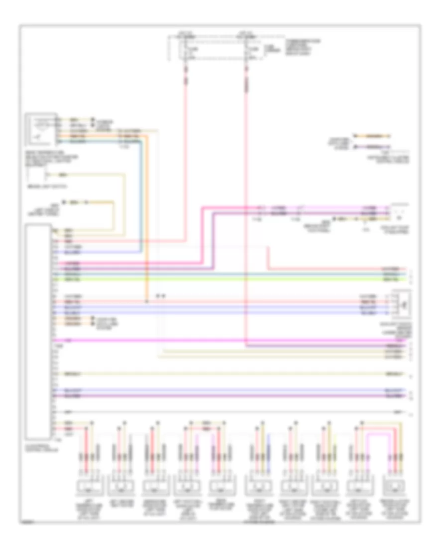
Электросхема кондиционера, Комфорт (1 из 3) для Audi A4 2.0T Quattro 2011
Электросхема кондиционера, Комфорт (1 из 3) для Audi A4 2.0T Quattro 2011 - Список элементов:
- 10a
- 3.0l
- Air flow door motor (left side of air intake housing)
- Brake light switch
- Climatronic control module
- Computer data lines system
- Coolant pump (if equipped)
- Defroster door motor (left side of a/c unit)
- Fuse 10a
- Fuse 40a
- Fuse carrier
- G638 (behind right kick panel)
- G687 (left side of center tunnel)
- Hot at all times
- Instrument cluster control module
- Interior lights system
- Left center vent motor
- Left footwell door motor (left side of a/c unit)
- Left temperature door motor (left side of a/c unit)
- Passenger's side fuse panel (behind right end of dash)
- Rear temperature flap motor
- Rear temperature selection potentiometer (w/ additional lighting equipment)
- Recirculation door motor (left side of air intake housing)
- Red
- Right center vent motor (left side of air intake housing)
- Right footwell door motor (lower left side of air intake housing)
- Right temperature door motor (top left side of air intake housing)
- Sunlight photo sensor (under center of dash)
- T16i
- T17b
- T17d
- T20e
- T32f
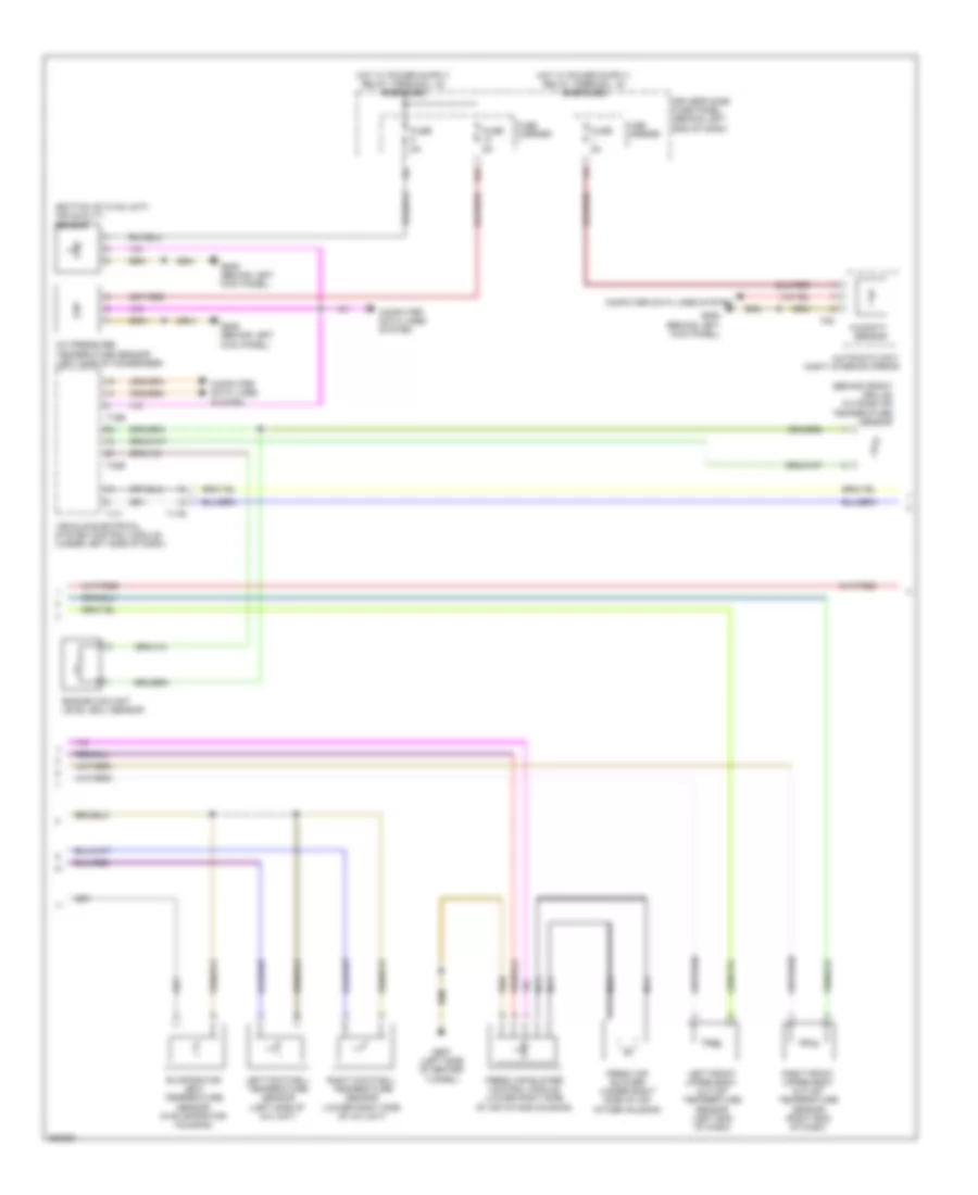
Электросхема кондиционера, Комфорт (2 из 3) для Audi A4 2.0T Quattro 2011
Электросхема кондиционера, Комфорт (2 из 3) для Audi A4 2.0T Quattro 2011 - Список элементов:
- (behind front grille) outside air temperature sensor
- (bottom of hvac unit) air quality sensor
- 12a
- A/c pressure/ temperature sensor (left side of condenser)
- Automatic day/ night interior mirror
- Computer data lines system
- Driver's side fuse panel (behind left end of dash)
- Engine coolant level (ecl) sensor
- Evaporator vent temperature sensor (in evaporator housing)
- Fresh air blower (under right side of air intake housing)
- Fresh air blower control module (lower right side of air intake housing)
- Fuse 5a
- Fuse carrier
- G639 (behind left kick panel)
- G687 (left side of center tunnel)
- Humidity sensor
- Left footwell temperature sensor (left side of a/c unit)
- Left front upper body outlet temperature sensor (left end of dash)
- Nca
- Right footwell temperature sensor (lower right side of a/c unit)
- Right front upper body outlet temperature sensor (right end of dash)
- T16b
- T17i
- T17r
- T32b
- T8c
- Vehicle electrical system control module (under left side of dash)
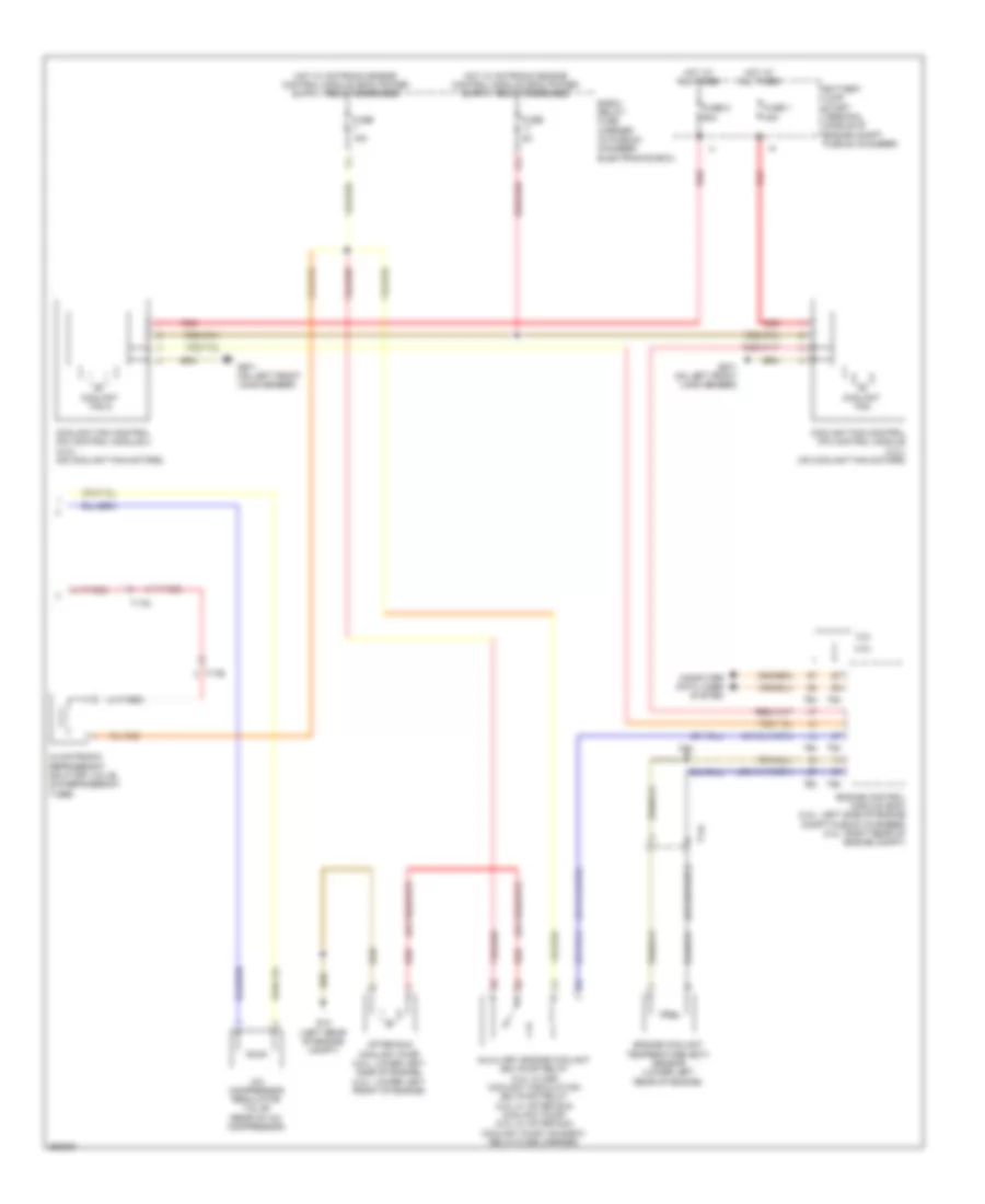
Электросхема кондиционера, Комфорт (3 из 3) для Audi A4 2.0T Quattro 2011
Электросхема кондиционера, Комфорт (3 из 3) для Audi A4 2.0T Quattro 2011 - Список элементов:
- 11a
- 2.ol
- 3.0l
- A/c compressor regulator valve (rear of a/c compressor)
- After run coolant pump (2.0l: lower left side of engine) (3.0l: lower left front of engine)
- Auxiliary engine coolant (ec) pump relay (3.0l w/ 8z9) coolant circulation (ec) pump relay (2.0l w/ after run coolant pump) (2.0l w/ after run coolant pump: on e-box relay/fuse carrier)
- Battery jump start terminal (middle of engine compt plenum chamber)
- Climatronic refrigerant shut-off valve (on refrigerant tube)
- Computer data lines system
- Coolant fan
- Coolant fan 2
- Coolant fan control (fc) control module (3.0l) (on coolant fan motors)
- Coolant fan control (fc) control module 2 (3.0l) (on coolant fan motors)
- E-box relay/ fuse carrier (in plenum chamber electronics box)
- Engine control module (ecm) (2.0l: left side of engine compt plenum chamber) (3.0l: right rear of engine compt)
- Engine coolant temperature (ect) sensor (lower left rear of engine)
- Fuse 1 40a
- Fuse 15a
- Fuse 2 60a
- Fuse 5a
- G12 (left rear of engine compt)
- G671 (on left front long member)
- Hot at all times
- Red
- T14f
- T17b
- T17q
- T60
- T94