POWER DISTRIBUTION
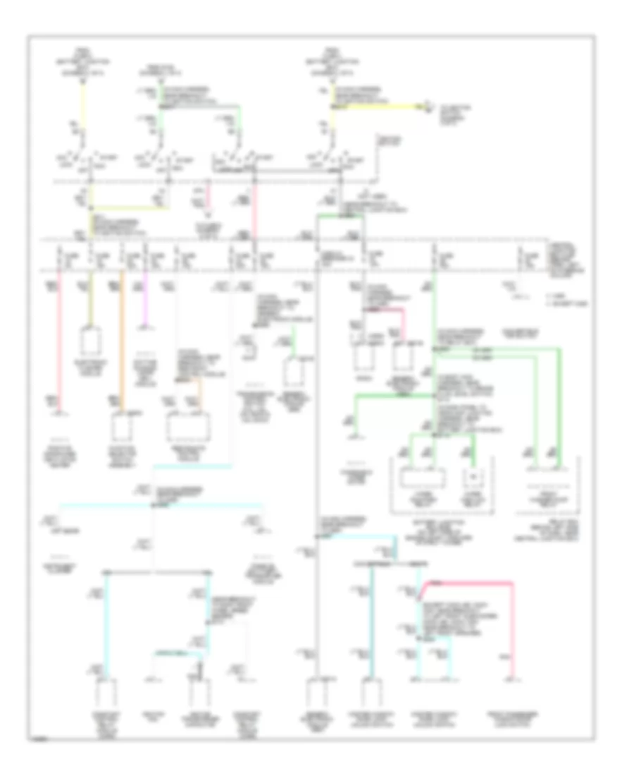
Power Distribution Wiring Diagram (1 of 3) for Ford Mustang GT 2004
 https://portal-diagnostov.com/license.html
Automotive Electricians Portal FZCO
Automotive Electricians Portal FZCO
https://portal-diagnostov.com/license.html
https://portal-diagnostov.com/license.html
Automotive Electricians Portal FZCO
Automotive Electricians Portal FZCO
List of elements for Power Distribution Wiring Diagram (1 of 3) for Ford Mustang GT 2004:
- (3.8l/3.9l: near breakout to c1019) (4.6l: near breakout to mass airflow sensor) s108
- (4.6l sohc, 4.6l dohc: near breakout to c1147)
- (4.6l super charged) (on right side of engine compt, on fender)
- (except mach 460, mach 1000: near breakout to convertible top motor) (mach 460, mach 1000: near breakout to front subwoofer amplifier) s409
- (except mach 460, mach 1000: near breakout to left front subwoofer) (mach 460, mach 1000: near breakout to left front speaker)
- (in body main harness, near breakout to generic electronic module) s269
- (in main harness, near breakout to c260) s270
- (in main harness, near breakout to main light switch) s233
- (in main harness, near breakout to main light switch) s242
- (near breakout to c146) s107
- (near breakout to c192) s105
- (near breakout to rear window defrost relay) s278
- (near breakout to relay box) s202
- 3.8l
- 4.6l
- Abs control module
- Auxiliary fuse box
- Battery
- Battery junction box (bjb) (on left side of engine compt, forward of strut tower)
- C102c c102a
- C201a
- C201b
- C202a
- C4157a
- C4158a
- C4159a
- C4160a
- C537 c508
- Central junction box (cjb) (behind dash, left of steering column)
- Charge air cooler pump relay
- Circuit breaker 30a
- Constant control relay module (ccrm)
- Convertible
- Convertible top lower relay
- Convertible top raise relay
- Data link connector (dlc)
- Daytime running lamps (drl) module
- Driver's seat adjust switch
- Electronic flasher module
- Except convertible
- Exterior rear view mirror switch
- Fog lamp relay
- Front cigar lighter
- Front passenger window/ door lock switch
- Fuse 10a
- Fuse 15a
- Fuse 20a
- Fuse 25a
- Fuse 30a
- Fuse 40a
- Fuse 50a
- G203 (behind center of dash)
- Generator
- Generic electronic module (gem)
- Horn relay
- Luggage compt lid release relay
- Luggage compt lid release switch
- Main light switch
- Master window/ door lock/ unlock switch
- Multi- function switch
- Nca
- Park lamp relay
- Power point
- Rear window defrost relay
- Red
- Relay box (behind left side of dash, near central junction box)
- S102
- S109 (near breakout to c192)
- S127 (in breakout to battery junction box)
- S268 (in main harness, near breakout to relay box)
- Starter motor
- Starter relay
- Subwoofer amplifier (luggage compt left inboard)
- Subwoofer amplifier (luggage compt left outboard)
- Subwoofer amplifier (luggage compt right inboard)
- Subwoofer amplifier (luggage compt right outboard)
- To fuse 27 (diagram 3 of 3)
- To ignition switch (diagram 2 of 3)
- To splice s215 (diagram 2 of 3)
- To splice s217 (diagram 2 of 3)
- W/ 4.6l dohc
- W/o 4.6l dohc
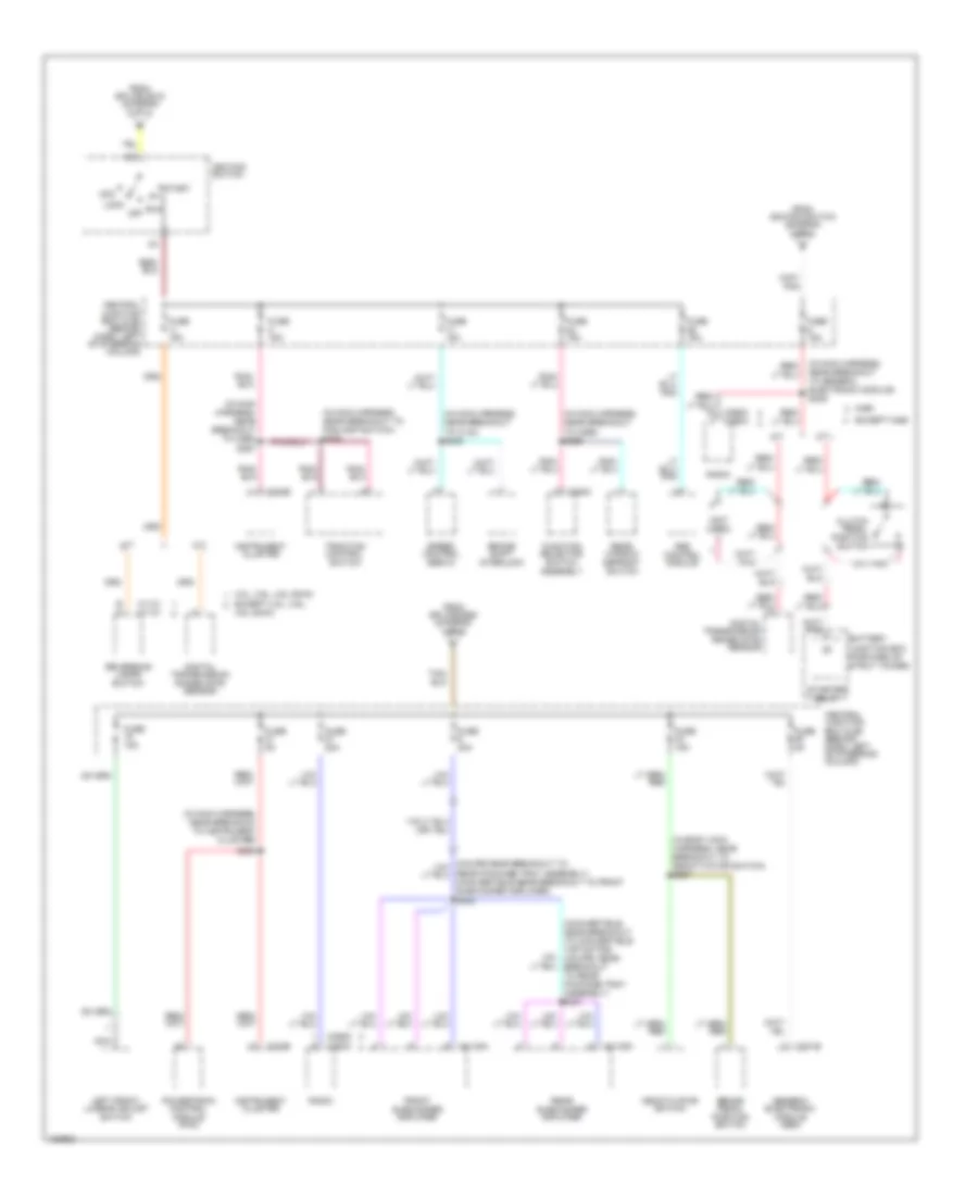
Power Distribution Wiring Diagram (2 of 3) for Ford Mustang GT 2004
List of elements for Power Distribution Wiring Diagram (2 of 3) for Ford Mustang GT 2004:
- (except mach 460, mach 1000: near breakout to left front subwoofer) (mach 460, mach 1000: near breakout to left front speaker) s505
- (in dash panel to headlamp junction harness, near breakout to battery junction box) s113
- (in main harness, near breakout to c260) s265
- (in main harness, near breakout to c260) s267
- (in main harness, near breakout to generic electronic module) s262
- (in main harness, near breakout to ignition switch) s215
- (in main harness, near breakout to ignition switch) s217
- (in main harness, near breakout to relay box) s225
- (in main harness, near breakout to restraint control module) s243
- (near breakout to central junction box) s264
- (near breakout to right front wheel speed sensor) s174
- (not used)
- 3.8l
- 4.6l
- Acc
- Battery junction box (bjb) (on left side of engine compt, forward of strut tower)
- C201a
- C201e
- C220b
- C290a
- C290d
- C294c
- Central junction box (cjb) (behind dash, left of steering column)
- Circuit breaker 43 20a
- Constant control relay module (ccrm)
- Convertible
- Convertible top switch
- Coupe
- Daytime running lamps (drl) module
- Electronic flasher module
- Except m460
- From fuse 4 (battery junction box) (diagram 1 of 3)
- From fuse 5 (battery junction box) (diagram 1 of 3)
- From s109 (diagram 1 of 3)
- Front passenger window/door lock switch
- Front washer pump relay
- Function selector switch assembly
- Fuse 15a
- Fuse 20a
- Fuse 2a
- Fuse 30a
- Generic electronic module (gem)
- Ignition coil
- Ignition switch
- Ignition transformer capacitor
- Instrument cluster
- Lock
- M460
- Master window/ door lock/ unlock switch
- Nca
- Off
- Passive anti-theft transceiver module
- Pnk
- Positive crankcase ventilation heater
- Radio
- Relay box (behind left side of dash, near central junction box)
- Restraints control module
- Run
- S211 (in main harness, near breakout to ignition switch)
- Sta
- Start
- To fuse 6 diagram (3 of 3)
- To ignition switch (diagram 3 of 3)
- Transmission control switch (3.8l, 3.9l, 4.6l sohc & 4.6l dohc)
- Windshield wiper motor
- Wiper high/low relay
- Wiper run/park relay
Power Distribution Wiring Diagram (3 of 3) for Ford Mustang GT 2004
List of elements for Power Distribution Wiring Diagram (3 of 3) for Ford Mustang GT 2004:
- (convertible: near breakout to convertible top motor) (coupe: near breakout to rear package tray assembly) s431
- (in body main harness, near breakout to deactivator switch) s207
- (in main harness, near breakout to c134) s245
- (in main harness, near breakout to c265) s256
- (in main harness, near breakout to c265) s257
- (in main harness, near breakout to foglamp switch) s284
- (in main harness, near breakout to generic electronic module) s239
- (in main harness, near breakout to instrument cluster)
- (not used)
- 3.8l, 3.9l, 4.6l dohc
- 4.6l dohc
- A/t
- Abs control module
- Acc
- B a
- Battery junction box (forward of strut tower)
- Brake pedal position switch
- Brake shift interlock
- C1131 c1131
- C201b
- C220b
- C290a
- C290d
- C290d c290a
- C294c
- C4108a
- C4109a
- Central junction box (cjb) (behind dash, left of steering column)
- Clutch pedal position switch
- Deactivator switch
- Digital transmission range (dtr) sensor
- Except 3.8l, 3.9l,
- Except m460
- From ignition switch (diagram 2 of 3)
- From splice s215 (diagram 2 of 3)
- From splice s260 (diagram 1 of 3)
- Front subwoofer amplifier
- Function selector switch assembly
- Fuse 15a
- Fuse 20a
- Fuse 30a
- Fuse 5a
- Generic electronic module (gem)
- Ignition switch
- Instrument cluster
- Left front, lumbar adjust switch
- Lock
- M/t
- M460
- Nca
- Off
- Powertrain control module (pcm)
- Radio
- Rear package tray assembly) (convertible:near breakout to front subwoofer amplifier) s432
- Rear subwoofer amplifier
- Rear window defrost switch
- Reversing lamps switch
- Run
- S259
- Speed control servo
- Start
- Starter relay
- Traction control switch

 Čeština
 Dansk
Dansk Deutsch
 Ελληνικά
 English
 English
 Español
 Suomi
Suomi Français
 עברית
עברית Hrvatski
 Magyar
 Italiano
 日本語
日本語 한국어
한국어 Nederlands
 Polski
 Português
 Português
 Română
 Русский
 Slovenčina
 Slovenščina
 Svenska
 Türkçe
 中文 (中国)