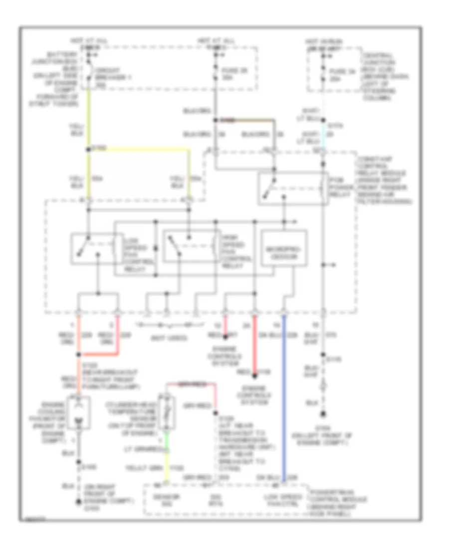
COOLING FAN
3.8L
3.8L, Cooling Fan Wiring Diagram for Ford Mustang GT 2004
 https://portal-diagnostov.com/license.html
Automotive Electricians Portal FZCO
Automotive Electricians Portal FZCO
https://portal-diagnostov.com/license.html
https://portal-diagnostov.com/license.html
Automotive Electricians Portal FZCO
Automotive Electricians Portal FZCO
List of elements for 3.8L, Cooling Fan Wiring Diagram for Ford Mustang GT 2004:
- (not used)
- (on right front of engine compt) g103
- Battery junction box (bjb) (on left side of engine compt, forward of strut tower)
- Central junction box (cjb) (behind dash, left of steering column)
- Circuit breaker 1 30a
- Constant control relay module (inside right front fender, behind air filter housing)
- Cylinder head temperature sensor (on top front of engine)
- Engine controls system
- Engine cooling fan motor (front of engine compt)
- Fuse 26 30a
- Fuse 34 20a
- G104 (on left front of engine compt)
- High speed fan control relay
- Hot at all times
- Hot in run or start
- Low speed fan control relay
- Low speed fan ctrl
- Micropro- cessor
- Pcm power relay
- Powertrain control module (behind right kick panel)
- Red
- Red/
- S100
- S102
- S108
- S115
- S122 (near breakout to right front park/turn lamp)
- S126 (a/t: near breakout to transmission hardware unit) (m/t: near breakout to c1168)
- S174
- Sensor sig
- Sig rtn
3.9L
3.9L, Cooling Fan Wiring Diagram for Ford Mustang GT 2004
List of elements for 3.9L, Cooling Fan Wiring Diagram for Ford Mustang GT 2004:
- (not used)
- (on right front of engine compt) g103
- Battery junction box (bjb) (on left side of engine compt, forward of strut tower)
- Central junction box (cjb) (behind dash, left of steering column)
- Circuit breaker 1 30a
- Constant control relay module (inside right front fender, behind air filter housing)
- Cylinder head temperature sensor (on top front of engine)
- Engine controls system
- Engine cooling fan motor (front of engine compt)
- Fuse 26 30a
- Fuse 34 20a
- G104 (on left front of engine compt)
- High speed fan control relay
- Hot at all times
- Hot in run or start
- Low speed fan control relay
- Low speed fan ctrl
- Micropro- cessor
- Pcm power relay
- Powertrain control module (behind right kick panel)
- Red
- Red/
- S100
- S102
- S108
- S115
- S122 (near breakout to right front park/turn lamp)
- S126 (a/t: near breakout to transmission hardware unit) (m/t: near breakout to c1168)
- S174
- Sensor sig
- Sig rtn
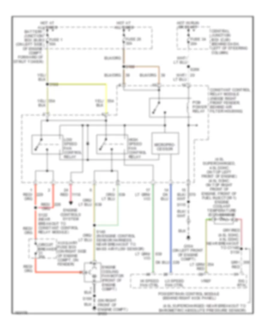
4.6L
4.6L, Cooling Fan Wiring Diagram for Ford Mustang GT 2004
List of elements for 4.6L, Cooling Fan Wiring Diagram for Ford Mustang GT 2004:
- (4.6l sohc, 4.6l dohc: near breakout to c1148) s130
- (4.6l supercharged, 4.6l dohc: on top left front of engine) (4.6l sohc: on top right front of engine, front of fuel injector 1)
- (4.6l supercharged: near breakout to barometric absolute pressure sensor)
- (on right front of engine compt) g103
- Auxiliary fuse box (on right side of engine compt, on fender)
- Battery junction box (bjb) (on left side of engine compt, forward of strut tower)
- Central junction box (cjb) (behind dash, left of steering column)
- Circuit breaker 30a
- Constant control relay module (inside right front fender, behind air filter housing)
- Engine controls system
- Engine coolant temperature (ect) sensor
- Engine cooling fan motor (front of engine compt)
- Fuse 1 50a
- Fuse 26 30a
- Fuse 34 20a
- G104 (on left front of engine compt)
- Hi speed fan ctrl
- High speed fan control relay
- Hot at all times
- Hot in run or start
- Lo speed fan ctrl
- Low speed fan control relay
- Micropro- cessor
- Pcm power relay
- Powertrain control module (behind right kick panel)
- Red
- S100
- S102
- S108
- S115
- S122 (near breakout to constant control relay module)
- S140 (in engine control sensor harness, near breakout to mass air flow sensor)
- S266
- Sig rtn
- Vref

 Čeština
 Dansk
Dansk Deutsch
 Ελληνικά
 English
 English
 Español
 Suomi
Suomi Français
 Français
 עברית
עברית Magyar
 Italiano
 日本語
日本語 한국어
한국어 Nederlands
 Polski
 Português
 Português
 Română
 Русский
 Slovenčina
 Slovenščina
 Svenska
 Türkçe
 中文 (中国)