
 Čeština
 Dansk
Dansk Deutsch
 Ελληνικά
 English
 English
 Español
 Suomi
Suomi Français
 Français
 עברית
עברית Magyar
 Italiano
 日本語
日本語 한국어
한국어 Nederlands
 Polski
 Português
 Português
 Română
 Русский
 Slovenčina
 Slovenščina
 Svenska
 Türkçe
 中文 (中国)

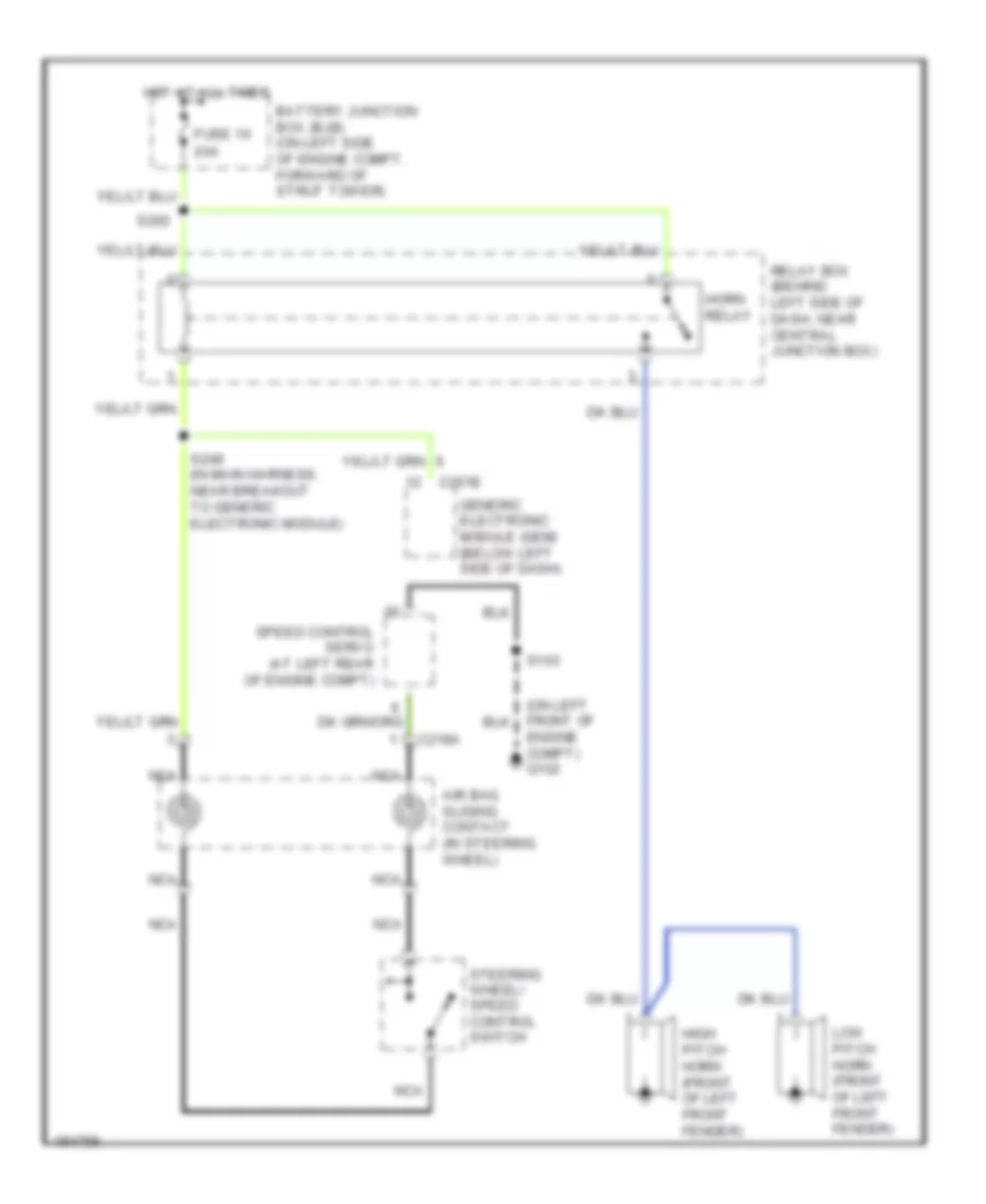
HORN
Horn Wiring Diagram for Ford Mustang GT 2004
List of elements for Horn Wiring Diagram for Ford Mustang GT 2004:

ANTI-LOCK BRAKESAIR CONDITIONINGANTI-THEFTCOOLING FANCOMPUTER DATA LINESDEFOGGERSBODY CONTROL MODULESCRUISE CONTROLEXTERIOR LIGHTSENGINE PERFORMANCEHEADLIGHTSGROUND DISTRIBUTIONHORNPOWER DOOR LOCKSINTERIOR LIGHTSPOWER MIRRORSINSTRUMENT CLUSTERPOWER DISTRIBUTIONPOWER WINDOWSPOWER TOP/SUNROOFPOWER SEATSSUPPLEMENTAL RESTRAINTSSHIFT INTERLOCKTRUNK, TAILGATE, FUEL DOORSTARTING/CHARGINGWARNING SYSTEMSTRANSMISSIONRADIOWIPER/WASHER