SUPPLEMENTAL RESTRAINTS
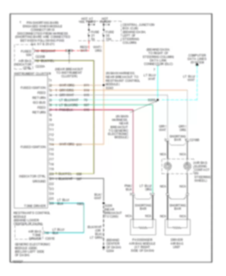
Supplemental Restraints Wiring Diagram for Ford Mustang GT 2004
List of elements for Supplemental Restraints Wiring Diagram for Ford Mustang GT 2004:
- (behind center of dash) g204
- (behind dash, to right of steering column) data link connector (dlc)
- (in main harness, near breakout to generic electronic module)
- (in main harness, near breakout to restraint control module) s243
- (near breakout to instrument cluster)
- (or
- Air bag
- Air bag sliding contact (in steering wheel)
- Air bag tone driver
- C201e
- C218b
- C220a
- C220b
- Central junction box (cjb) (behind dash, left of steering column)
- Computer data lines system
- Driver air bag unit
- Feed
- Fuse 15a
- Fuse 5a
- Fused ign
- Fused ignition
- Generic electronic module (gem) (below left side of dash)
- Ground
- Hot at all times
- Hot in run
- Indicator ctrl
- Instrument cluster
- Iso bus
- Nca
- Passenger air bag module (at right side of dash)
- Pin shorting bars engaged when module connector is disconnected from harness (shorting bars are connected between following pins: 3-4, 6-7 & 20-21)
- Restraints control module (behind lower center of dash)
- Return
- S205 (near breakout to c260)
- S255
- S259
- Shorting bar
- Tone driver
 Čeština
 Dansk
Dansk Deutsch
 Ελληνικά
 English
 English
 Español
 Suomi
Suomi Français
 Français
 עברית
עברית Magyar
 Italiano
 日本語
日本語 한국어
한국어 Nederlands
 Polski
 Português
 Português
 Română
 Русский
 Slovenčina
 Slovenščina
 Svenska
 Türkçe
 中文 (中国)
 Hrvatski