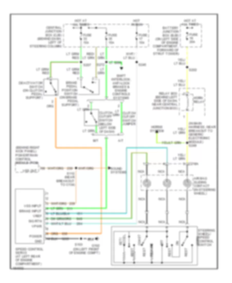
CRUISE CONTROL
Cruise Control Wiring Diagram for Ford Mustang GT 2004
 https://portal-diagnostov.com/license.html
Automotive Electricians Portal FZCO
Automotive Electricians Portal FZCO
https://portal-diagnostov.com/license.html
https://portal-diagnostov.com/license.html
Automotive Electricians Portal FZCO
Automotive Electricians Portal FZCO
List of elements for Cruise Control Wiring Diagram for Ford Mustang GT 2004:
- (behind right kick panel)
- (in main harness, near breakout to generic electronic module) s249
- A/t
- Accel set/
- Air bag sliding contact (in steering wheel)
- Battery junction box (bjb) (on left side of engine compartment, forward of strut tower)
- Brake input
- Brake pedal position switch (on brake pedal support)
- C218a
- Central junction box (cjb) (behind dash, left of steering column)
- Clutch cutoff switch (below left side of dash)
- Coast
- Deactivator switch (on clutch pedal support)
- Fuse 15a
- Fuse 20a
- G102 (on left front of engine compt)
- Gnd
- Horn relay
- Horns system
- Hot at all times
- Hot in run
- M/t
- Nca
- Off
- Power
- Powertrain control module (pcm)
- Relay box (behind left side of dash, near central junction box)
- Rest
- Resume
- S103
- S112 (near breakout to c134)
- S202
- S207
- S245
- S272
- Shift interlock, anti-lock brakes & engine controls systems
- Sig rtn
- Sound systems
- Speed control servo (at left rear of engine compartment)
- Steering wheel/ speed control switch horn
- Vpwr
- Vref
- Vss input
- Vss out
 Čeština
 Dansk
Dansk Deutsch
 Ελληνικά
 English
 English
 Español
 Suomi
Suomi Français
 Français
 עברית
עברית Hrvatski
 Magyar
 Italiano
 日本語
日本語 한국어
한국어 Nederlands
 Polski
 Português
 Português
 Română
 Русский
 Slovenčina
 Slovenščina
 Svenska
 Türkçe
 中文 (中国)
