AIR CONDITIONING
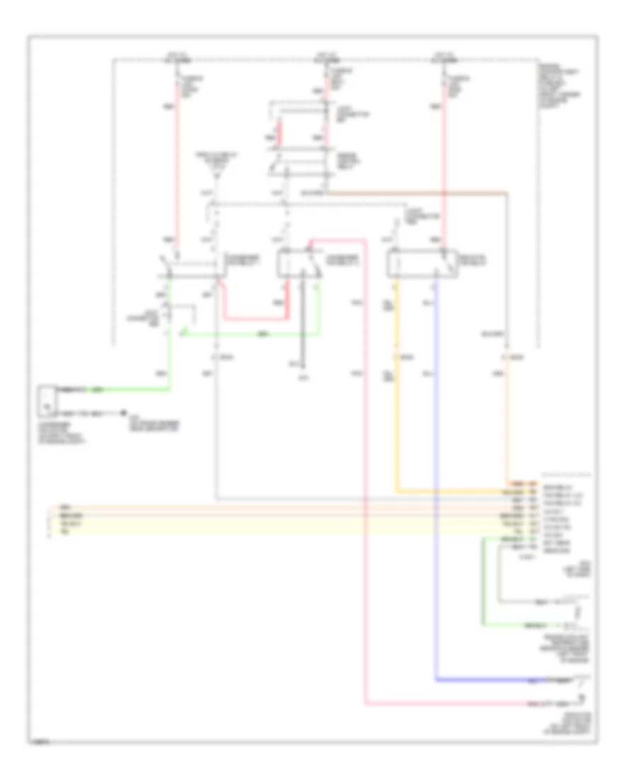
Manual A/C Wiring Diagram (1 of 2) for Hyundai Elantra GT 2004

List of elements for Manual A/C Wiring Diagram (1 of 2) for Hyundai Elantra GT 2004:
- (beside blower motor, below right side of dash) blower relay
- A/c compressor (right front of engine)
- A/c control module (below center of dash, forward of shift lever)
- A/c on sig
- A/c relay
- Actuator
- Blower motor (under right side of dash)
- Blower resistor (under right side of dash, in blower motor housing)
- Blower switch
- Blr on sig
- Cool
- Defog switch
- Defogger system
- Ec05
- Engine compartment relay & fuse box (in left front corner of engine compt)
- F/b
- F/b ground
- Fre
- Fuse 10a
- Fuse 15a
- Fusible link (blower) 30a
- G11 (behind center of dash)
- Ground
- High
- Horn & a/c fuse 15a
- Hot at all times
- Hot in on
- I/p-g
- I/p-h
- I/p-j
- Iii
- Iiii
- Illum +
- Illum -
- Intake actuator (behind upper right side of dash)
- Interior lights system
- Joint connector m36 (left side of dash)
- Low
- Mem pwr
- Mid
- Mode actuator (behind left center of dash)
- Nca
- Off
- On input
- Passenger compartment junction block (under left side of dash, near kick panel)
- Pnk
- Rec
- Red
- Temperature actuator (behind lower left center of dash)
- Thermistor
- Thermostatic switch (behind right side of dash)
- To joint connector e58 (diagram 2 of 2)
- Triple pressure switch (on a/c line, near right front strut tower)
- Vcc
- Warm
Manual A/C Wiring Diagram (2 of 2) for Hyundai Elantra GT 2004
List of elements for Manual A/C Wiring Diagram (2 of 2) for Hyundai Elantra GT 2004:
- A/c rly
- A/c sig
- A/c sw on
- C fan sig
- C183-1
- Condenser fan motor (on right front of engine compt)
- Condenser fan relay 1
- Condenser fan relay 2
- Ec05
- Ec06
- Ect sens
- Eng relay
- Engine compartment relay & fuse box (in left front corner of engine compt)
- Engine control relay
- Engine coolant temperature sensor & sender (left front of engine)
- Fan relay (hi)
- Fan relay (lo)
- From a/c relay (diagram 1 of 2)
- Fusible link (cond) 20a
- Fusible link (ecu) 20a
- Fusible link (rad) 20a
- G15
- G16 (on frame member, near genarator)
- Hot at all times
- Joint connector e57
- Joint connector e58
- Joint connector e59
- Nca
- Pcm (left side of dash)
- Pnk
- Radiator fan motor (on left front of engine compt)
- Radiator fan relay
- Red
- Sens gnd