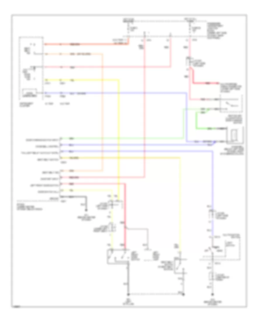
WARNING SYSTEMS
Warning Systems Wiring Diagram for Hyundai Elantra GT 2004
List of elements for Warning Systems Wiring Diagram for Hyundai Elantra GT 2004:
- (w/ trip)
- (w/o trip)
- Chime bell (below left side of dash, right of steering column)
- Chime bell control
- Door ajar ind
- Door switch (all)
- Door warning switch input
- Etacm (under center of dash, below radio)
- Fuse 2 10a
- Fuse 25 15a
- G01 (left "b" pillar)
- G11 (behind center of dash)
- G12 (behind center of dash)
- Ground
- Head
- Hot at all times
- Hot in on or start
- I/p-g
- I/p-h
- Ignition key illumination & door warning switch
- Instrument cluster
- J/c m27 (center of dash)
- J/c m33 (left side of dash)
- J/c m36 (left side of dash)
- J/c m46 (under left front seat)
- Left front door lamp
- Left front door switch
- Light switch
- M01-2
- M09-1
- M09-2
- M10-1
- M10-2
- M25-1
- M25-2
- Micro computer
- Multifunction switch
- Multipurpose check connector (lower left side of dash)
- Nca
- Off
- On/start input
- Park
- Passenger compartment junction block (under left side of dash, near kick panel)
- Red
- Seat belt ind
- Seat belt switch
- Seat belt switch (in seat belt buckle)
- Taillight relay auto cut cntrl
- W/ trip
- W/o trip
 English