DEFOGGERS
Defoggers Wiring Diagram for Hyundai Elantra GT 2004
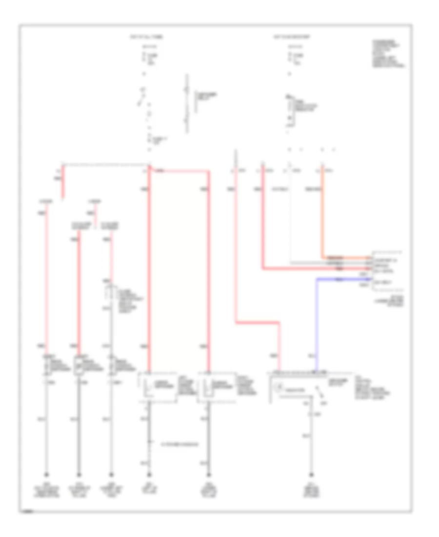
List of elements for Defoggers Wiring Diagram for Hyundai Elantra GT 2004:
- 4 door
- 5 door
- A/c control module (below center of dash, forward of shift lever)
- Defogger
- Defogger relay
- Defogger switch
- Etacm (under center of dash)
- Fuse 10a
- Fuse 17 10a
- Fuse 30a
- G01 (left "b" pillar)
- G03 (under right "b" pillar)
- G10 (at base of right "c" pillar)
- G11 (behind center of dash)
- G28 (on tailgate, near rear wiper motor)
- G29 (under left "c" pillar trim)
- Glass antenna (above right end of package shelf)
- Hot at all times
- Hot in on or start
- I/p-d
- I/p-f
- I/p-g
- I/p-h
- Indicator
- Left outside mirror motor & defogger
- M20
- M25-1
- M25-2
- M66-1
- M69
- M75
- Mirror defogger
- Nca
- Off
- On/start in
- Passenger compartment junction block (under left side of dash, near kick panel)
- Pre- excitation resistor
- R06
- R15
- Rear
- Red
- Right outside mirror motor & defogger
- Rly cntrl
- Rpm sig
- Sw input
- W/ glass antenna
- W/ power windows
- W/o glass antenna
- Window
 English