POWER DISTRIBUTION
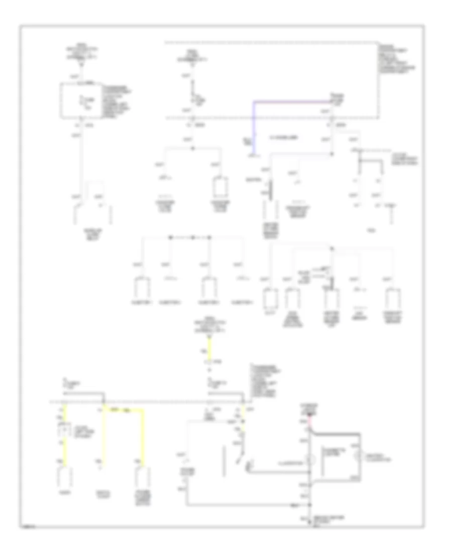
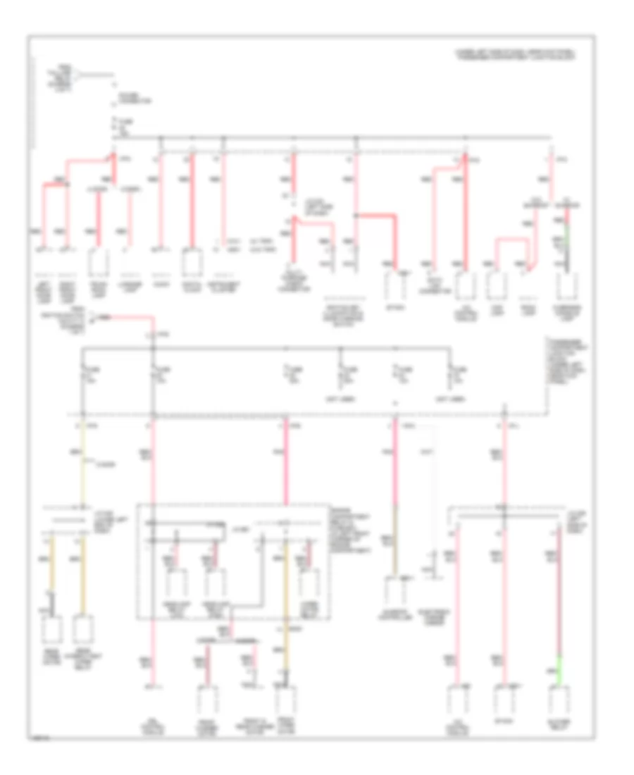
Power Distribution Wiring Diagram (1 of 7) for Hyundai Elantra GT 2004

List of elements for Power Distribution Wiring Diagram (1 of 7) for Hyundai Elantra GT 2004:
- (in left front corner of engine compartment) engine compartment relay & fuse box
- A/c relay
- A/t control relay
- Abs control module
- Acc
- Battery
- Battery ground
- Blower relay
- Body ground
- C183-1
- Condenser fan relay 1
- Condenser fan relay 2
- Drl control module
- Drl fuse 15a
- Ec05
- Ec06
- Ecu fuse 10a
- Engine control relay
- F/fog fuse 15a
- From fusible link (batt) a 120a (diagram 1 of 7)
- Front fog lamp relay
- Fuel pump relay
- Fusible link (abs 1) 30a
- Fusible link (abs 2) 30a
- Fusible link (batt) 120a
- Fusible link (batt) 50a
- Fusible link (blower) 30a
- Fusible link (cond) 20a
- Fusible link (ecu) 20a
- Fusible link (ign) 40a
- Fusible link (rad) 20a
- Generator
- H/lp (high) fuse 15a
- H/lp (low) fuse 15a
- Head- lamp relay (high)
- Head- lamp relay (low)
- Horn & a/c fuse 15a
- Horn relay
- Ignition coil
- Ignition switch
- J/c e55
- J/c e57
- J/c e58
- Joint connector e62
- Lock
- Nca
- Off
- Pcm
- Pnk
- Radiator fan relay
- Red
- Siren
- Start
- Start motor
- Start relay
- Start solenoid
- To fuse 13, 30a (diagram 3 of 7)
- To fusible link (ign) 40a (diagram 1 0f 7)
- To inj fuse 15a (diagram 2 of 7)
- To passenger compartment junction block (fuse 18, 15a) (diagram 2 of 7)
- To passenger compartment junction block (fuse 2, 10a) (diagram 7 of 7)
- To passenger compartment junction block (fuse 20, 10a) (diagram 6 of 7)
- To passenger compartment junction block (fuse 8, 10a) (diagram 2 of 7)
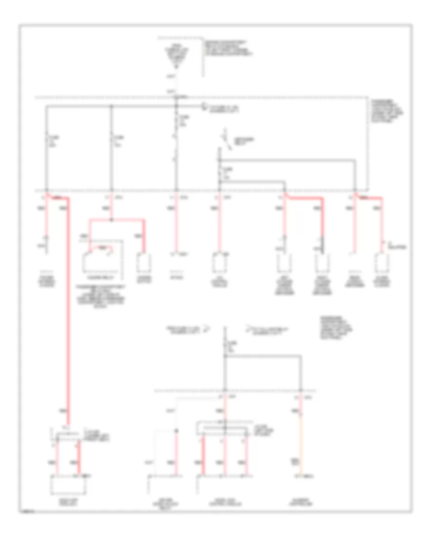
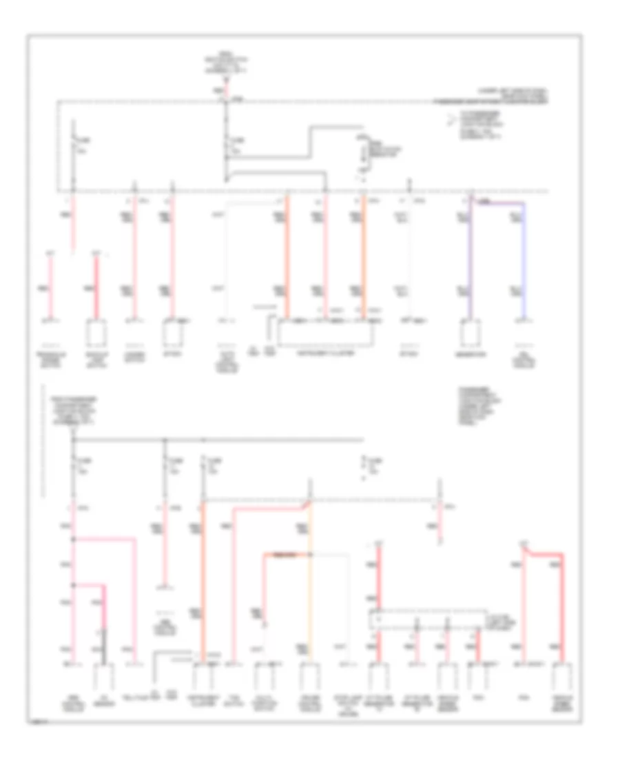
Power Distribution Wiring Diagram (2 of 7) for Hyundai Elantra GT 2004
List of elements for Power Distribution Wiring Diagram (2 of 7) for Hyundai Elantra GT 2004:
- (behind center of dash) g11
- (not used)
- Ashtray illumination
- Audio
- Burglar alarm relay
- C183-1
- Camshaft position sensor
- Canister close valve
- Canister purge valve
- Cigarette lighter
- Crankshaft position sensor
- Cvvt
- Digital clock
- Ec05
- Engine compartment relay & fuse box (in left front corner of engine compartment)
- From ignition switch (cavity 1) (diagram 1 of 7)
- From ignition switch (cavity 4) (diagram 1 of 7)
- From j/c e58 (diagram 1 of 7)
- Fuse 10a
- Fuse 18 15a
- Fuse 9 10a
- Heated oxygen sensor (down)
- Heated oxygen sensor (up)
- I/p-d
- I/p-e
- I/p-f
- I/p-g
- Idle speed control actuator
- Illumination
- Inj fuse 15a
- Injector 1
- Injector 2
- Injector 3
- Injector 4
- Interior lights system
- J/c c191 (lower right side of dash)
- J/c m33 (left side of dash)
- Maf sensor
- Nca
- Non- sulev
- Passenger compartment junction block (under left side of dash, near kick panel)
- Pcm
- Pnk
- Power outlet
- Power outside mirror switch
- Smatra
- Snsr fuse 1oa
- Sulev
- W/ immobilizer
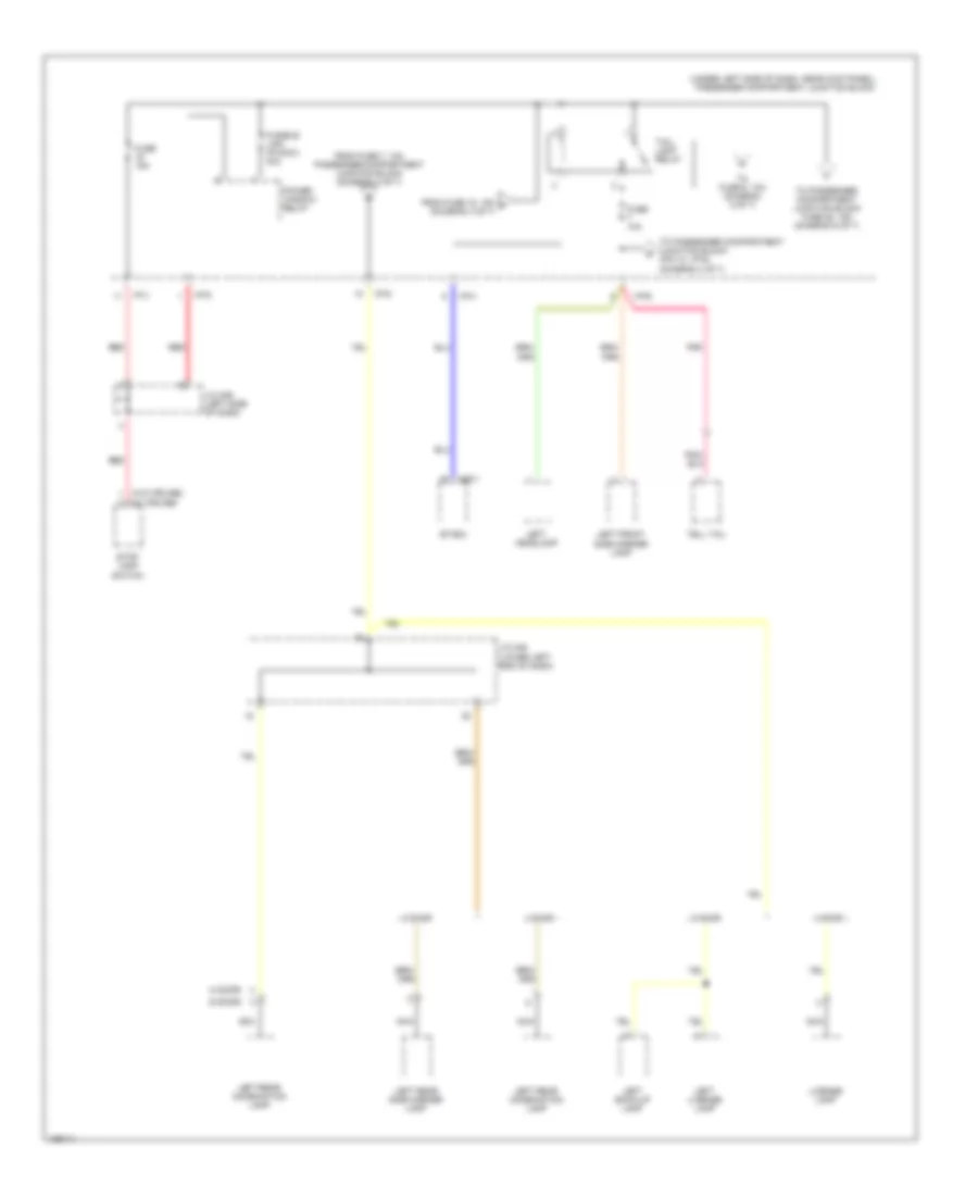
Power Distribution Wiring Diagram (3 of 7) for Hyundai Elantra GT 2004
List of elements for Power Distribution Wiring Diagram (3 of 7) for Hyundai Elantra GT 2004:
- A/c control module
- Audio amp module 2
- Defogger relay
- Door lock control module
- Driver door unlock relay
- Engine compartment relay & fuse box (in left front corner of engine compartment)
- Etacm
- From fuse 13, 30a (diagram 3 of 7)
- From fusible link (batt) 50a (diagram 1 of 7)
- Fuse 10a
- Fuse 15a
- Fuse 20a
- Fuse 30a
- Glass antenna (4 door)
- Hazard relay
- Hazard switch
- I/p-a
- I/p-c
- I/p-d
- I/p-f
- I/p-g
- I/p-h
- If equipped
- J/c m36 (left side of dash)
- J/c m49 (under left front seat)
- Left outside mirror motor & defogger
- M20
- M25-1
- M52-2
- M94-2
- Nca
- Passenger compartment junction block (under left side of dash, near kick panel)
- Passenger compartment relay box (under left side of dash, beside passenger compartment junction block)
- Power antenna (5 door)
- Rear window defogger
- Red
- Right outside mirror motor & defogger
- Sunroof controller
- To fuse 15, 15a (diagram 3 of 7)
- To taillamp relay (diagram 4 of 7)
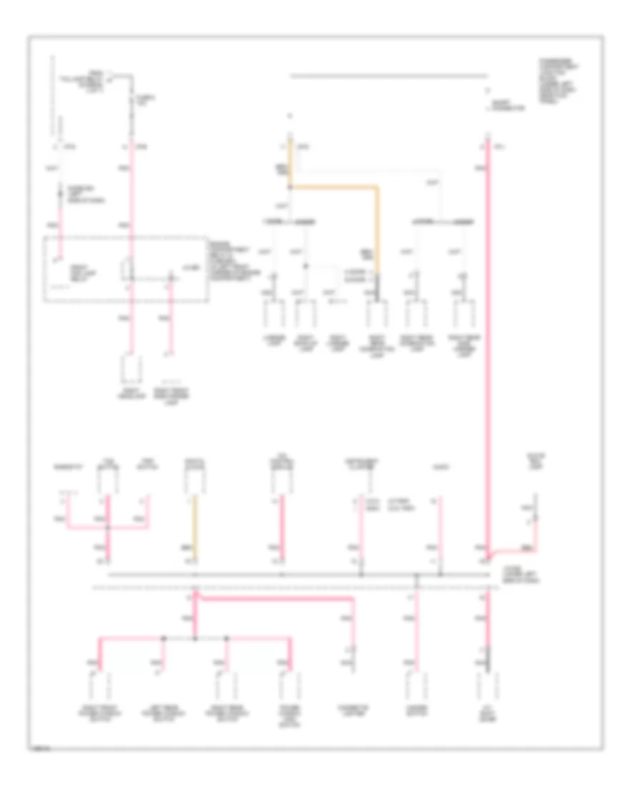
Power Distribution Wiring Diagram (4 of 7) for Hyundai Elantra GT 2004
List of elements for Power Distribution Wiring Diagram (4 of 7) for Hyundai Elantra GT 2004:
- (4 door)
- (5 door)
- (under left side of dash, near kick panel) passenger compartment junction block
- (w/ cruise)
- (w/o cruise)
- 4 door
- 5 door
- Etacm
- From fuse 15, 15a f (diagram 3 of 7)
- From fuse 7, 10a passenger compartment junction block (diagram 4 of 7)
- Fuse 10a
- Fuse 15a
- Fusible link (p/wdw) 30a
- I/p-b
- I/p-d
- I/p-g
- I/p-h
- I/p-j
- J/c m36 (left side of dash)
- J/c m45 (lower left end of dash)
- Left back-up lamp
- Left front side marker lamp
- Left headlamp
- Left license lamp
- Left rear combination lamp
- Left rear side marker lamp
- License lamp
- M25-1
- Nca
- Pnk
- Power window relay
- Red
- Stop lamp switch
- Tail- lamp relay
- Tell tail
- To fuse 6, 10a (diagram 5 of 7)
- To passenger compartment junction block (pin 10, i/p-d) (diagram 4 of 7)
- To passenger compartment junction block fuse 25, 15a (diagram 6 of 7)
Power Distribution Wiring Diagram (5 of 7) for Hyundai Elantra GT 2004
List of elements for Power Distribution Wiring Diagram (5 of 7) for Hyundai Elantra GT 2004:
- (4 door)
- (5 door)
- (w/o trip)
- (w/trip)
- 4 door
- 5 door
- A/c control module
- A/t shift lever
- Audio
- Cigarette lighter
- Digital clock
- Diode z02 (left side of dash)
- Engine compartment relay & fuse box (in left front corner of engine compartment)
- From taillamp relay h (diagram 4 of 7)
- Front fog lamp relay
- Fuse 6 10a
- Glove box lamp
- Hazard switch
- I/p-b
- I/p-d
- I/p-g
- I/p-j
- Instrument cluster
- J/c e61
- J/c m08 (lower left side of dash)
- Left rear power window switch
- License lamp
- M09-3
- M10-3
- Nca
- Passenger compartment junction block (under left side of dash, near kick panel)
- Pnk
- Power window main switch
- Red
- Rheostat
- Right back-up lamp
- Right front power window switch
- Right front side marker lamp
- Right headlamp
- Right license lamp
- Right rear combination lamp
- Right rear power window switch
- Right rear side marker lamp
- Short connector
- Tcs switch
- Trip switch
Power Distribution Wiring Diagram (6 of 7) for Hyundai Elantra GT 2004
List of elements for Power Distribution Wiring Diagram (6 of 7) for Hyundai Elantra GT 2004:
- (diagram 1 of 7)
- (diagram 4 of 7)
- (not used)
- (under left side of dash, near kick panel) passenger compartment junction block
- (w/ trip)
- (w/o trip)
- 4 door
- 5 door
- A/c control module
- Audio
- Blower relay
- Data link connector
- Digital clock
- Drl control module
- Ec05
- Electronic chrome mirror
- Engine compartment relay & fuse box (in left front corner of engine compartment)
- Etacm
- From ignition switch (cavity 3) e
- From taillamp relay i
- Front & rear washer motor
- Front washer motor
- Front wiper motor
- Fuse 10a
- Fuse 15a
- Fuse 20a
- Headlamp relay (high)
- Headlamp relay (low)
- I/p-b
- I/p-c
- I/p-d
- I/p-e
- I/p-g
- I/p-j
- Ignition key illumination & door warning switch
- Instrument cluster
- J/c e56
- J/c e61
- J/c m33 (left side of dash)
- J/c m36 (left side of dash)
- J/c m45 (lower left end of dash)
- Left front door lamp
- Luggage lamp
- M09-1
- M10-1
- M20
- M25-1
- M94-1
- Map lamp
- Multi- purpose check connector
- Nca
- Overhead console lamp
- Passenger compartment junction block (under left side of dash, near kick panel)
- Pnk
- Power connector
- Rear intermittent wiper relay
- Rear wiper motor
- Red
- Right front door lamp
- Room lamp
- Sunroof controller
- Trunk room lamp
- W/ sunroof
- W/o sunroof
- Wiper motor relay
Power Distribution Wiring Diagram (7 of 7) for Hyundai Elantra GT 2004
List of elements for Power Distribution Wiring Diagram (7 of 7) for Hyundai Elantra GT 2004:
- (fuse 3, 15a) (diagram 7 of 7)
- (under left side of dash, near kick panel) passenger compartment junction block
- A/t
- A/t pulse generator "a"
- A/t pulse generator "b"
- Abs control module
- Auto light control module
- Back-up lamp switch
- C183-1
- Cruise control module
- Drl control module
- Etacm
- From ignition switch (cavity 6) (diagram 1 of 7)
- From passenger compartment junction block (fuse 2, 10a) (diagram 7 of 7)
- Fuse 10a
- Fuse 15a
- Generator
- Hazard switch
- I/p-b
- I/p-e
- I/p-g
- I/p-h
- I/p-j
- I/p-k
- Instrument cluster
- J/c c192 (left side of dash)
- M/t
- M01-4
- M09-1
- M09-2
- M09-3
- M10-1
- M10-2
- M25-1
- Multi- function switch
- Nca
- Oc sensor
- Passenger compartment junction block (under left side of dash, near kick panel)
- Pcm
- Pnk
- Pre- excitation resistor
- Red
- Srs control module
- Stop lamp switch (w/ cruise)
- Tcs switch
- Telltale
- To passenger compartment junction block
- Transaxle range switch
- Vehicle speed sensor
- W/ trip
- W/o trip