HEADLIGHTS
Headlights Wiring Diagram, with Autolamps for Hyundai Elantra GT 2004

List of elements for Headlights Wiring Diagram, with Autolamps for Hyundai Elantra GT 2004:
- (behind center of dash) g12
- (center of dash) auto light control module
- (center of dash) joint connector m27
- (in left front corner of engine compt) engine compartment relay & fuse box
- (left side of dash) joint connector m36
- (under left side of dash, near kick panel) passenger compartment junction block
- (w/ trip)
- (w/o trip)
- +5v
- Air conditioning system
- Amp
- Amp gnd
- Auto
- Dimmer/ passing switch
- Diode z02 (left side of dash)
- Etacm (under center of dash, below radio)
- Flash
- Front fog fuse 15a
- Front fog lamp switch
- Front foglamp indicator
- Front foglamp relay
- Fuse 10a
- Fusible link (batt) fuse 50a
- G12 (behind center of dash)
- G15
- Gnd
- H/l
- Head
- Headlamp (high) fuse 15a
- Headlamp (low) fuse 15a
- Headlamp relay (high)
- Headlamp relay (low)
- High
- High beam indicator
- Hot at all times
- Hot in on
- Hot in on or start
- I/p-a
- I/p-b
- I/p-g
- I/p-h
- Input
- Instrument cluster
- Interior lights system
- Joint connector e56
- Joint connector e60
- Joint connector e62
- Joint connector m27 (center of dash)
- Left front fog lamp
- Left headlamp
- Light switch
- Low
- M01-2
- M09-1
- M09-3
- M10-2
- M10-3
- M25-1
- M25-2
- Mcu
- Multifunction switch
- Nca
- Off
- Park
- Passenger compartment junction block (under left side of dash, near kick panel)
- Photo sensor (on top right side of dash, near defroster vent)
- Pnk
- Red
- Right front fog lamp
- Right headlamp
- Sig in
- T/l
- Taillamp relay
- W/ trip
- W/o trip
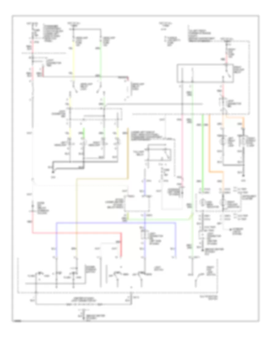
Headlights Wiring Diagram, with DRL (1 of 2) for Hyundai Elantra GT 2004
List of elements for Headlights Wiring Diagram, with DRL (1 of 2) for Hyundai Elantra GT 2004:
- (behind center of dash) g12
- (center of dash) joint connector m27
- (in left front corner of engine compt) engine compartment relay & fuse box
- Dimmer/ passing switch
- Drl resistor (on left fenderwell)
- Etacm (under center of dash, below radio)
- Flash
- From taillamp relay (diagram 2 of 2)
- Front fog lamp switch
- Fuse 10a
- G15
- Head
- Headlamp (high) fuse 15a
- Headlamp (low) fuse 15a
- Headlamp relay (high)
- Headlamp relay (low)
- High
- Hot at all times
- Hot in on
- I/p-b
- Joint connector e56
- Joint connector e60
- Joint connector m36 (left side of dash)
- Left headlamp
- Light switch
- Low
- M01-2
- M25-1
- M25-2
- Multifunction switch
- Off
- Park
- Passenger compartment junction block (under left side of dash, near kick panel)
- Pnk
- Right headlamp
- To drl control module (diagram 2 of 2)
- To front foglamp relay (diagram 2 of 2)
- To instrument cluster (diagram 2 of 2)
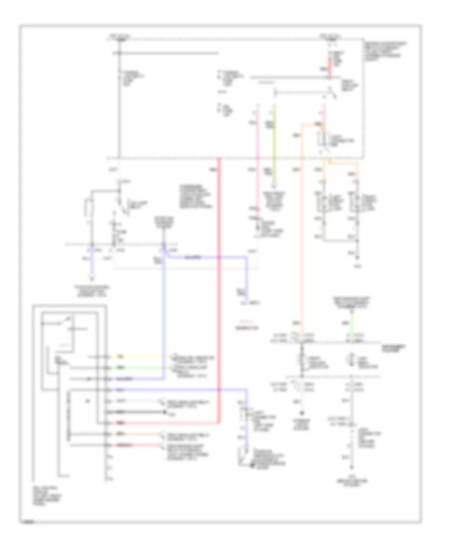
Headlights Wiring Diagram, with DRL (2 of 2) for Hyundai Elantra GT 2004
List of elements for Headlights Wiring Diagram, with DRL (2 of 2) for Hyundai Elantra GT 2004:
- (w/ trip)
- (w/o trip)
- Diode z02 (left side of dash)
- Drl control module (on left front inner fender panel)
- Drl fuse 15a
- Drl relay
- E20-2
- Engine compartment relay & fuse box (in left front corner of engine compt)
- From drl resistor (diagram 1 of 2)
- From engine compt relay & fuse box, (diagram 1 of 2)
- From engine compt relay & fuse box, joint connector e56 (diagram 1 of 2)
- From front fog lamp switch (diagram 1 of 2)
- From headlamp relay (diagram 1 of 2)
- Front fog fuse 15a
- Front foglamp indicator
- Front foglamp relay
- Fuse 10a
- Fusible link (batt) fuse 120a
- Fusible link (batt) fuse 50a
- G12 (behind center of dash)
- G15
- Generator
- High beam indicator
- Hot at all times
- I/p-a
- I/p-b
- I/p-g
- I/p-h
- Instrument instrument cluster cluster
- Interior lights system
- Joint connector e62
- Joint connector m27 (center of dash)
- Joint connector m36 (left side of dash)
- Left front fog lamp
- M09-1
- M09-3
- M10-2
- M10-3
- Nca
- Parking brake switch (on base of parking brake lever)
- Passenger compartment junction block (under left side of dash, near kick panel)
- Pnk
- Power & control circuit
- Red
- Right front fog lamp
- Starting/ charging system
- Taillamp relay
- To etacs control module/tacm (diagram 1 of 2)
- W/ trip
- W/o trip
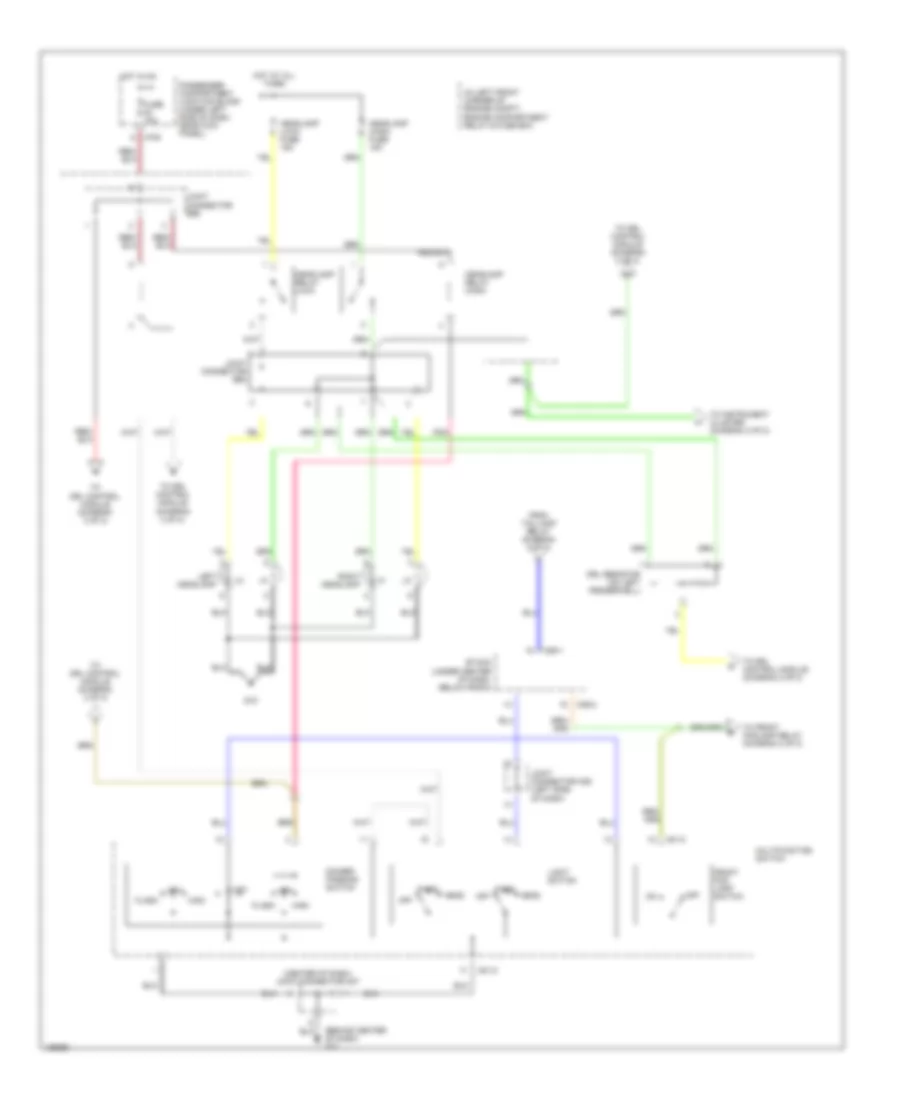
Headlights Wiring Diagram, without DRL for Hyundai Elantra GT 2004
List of elements for Headlights Wiring Diagram, without DRL for Hyundai Elantra GT 2004:
- (behind center of dash) g12
- (center of dash) joint connector m27
- (in left front corner of engine compt) engine compartment relay & fuse box
- (under left side of dash, near kick panel) passenger compartment junction block
- (w/ trip)
- (w/o trip)
- Dimmer/ passing switch
- Diode z02 (left side of dash)
- Diode z04 (below steering column)
- Etacm (under center of dash, below radio)
- Flash
- Front fog fuse 15a
- Front fog lamp switch
- Front foglamp indicator
- Front foglamp relay
- Fuse 10a
- Fusible link (batt) fuse 50a
- G15
- Head
- Headlamp (high) fuse 15a
- Headlamp (low) fuse 15a
- Headlamp relay (high)
- Headlamp relay (low)
- High
- High beam indicator
- Hot at all times
- Hot in on
- I/p-a
- I/p-b
- I/p-g
- I/p-h
- Instrument cluster
- Interior lights system
- Joint connector e56
- Joint connector e60
- Joint connector e62
- Joint connector m27 (center of dash)
- Joint connector m36 (left side of dash)
- Left front fog lamp
- Left headlamp
- Light switch
- Low
- M01-1
- M01-2
- M09-1
- M09-3
- M10-2
- M10-3
- M25-1
- M25-2
- Multifunction switch
- Nca
- Off
- Park
- Passenger compartment junction block (under left side of dash, near kick panel)
- Pnk
- Red
- Right front fog lamp
- Right headlamp
- Taillamp relay
- W/ trip
- W/o trip