ANTI-THEFT
Forced Entry Wiring Diagram for Hyundai Elantra GT 2004

List of elements for Forced Entry Wiring Diagram for Hyundai Elantra GT 2004:
- (behind center of dash) g11
- (left rear of engine compt) siren
- (rear of respective door)
- (under left side of dash, beside passenger compt junction block) passenger compartment relay box
- 4 door
- 5 door
- B/alarm rly cntrl
- Burglar alarm relay (below left side of dash, beside passenger compt relay block)
- Code save
- Dl rly cntrl (lk)
- Dl rly cntrl (unlk)
- Door locks system
- Door sw (all)
- Driver door key
- Driver door key lock/ unlock switch
- Driver door unlock relay
- Ec06
- Ecu fuse 10a
- Engine compartment relay & fuse box (in left front corner of engine compt)
- Etacm (under center of dash, below radio)
- Exterior lights system
- Fuse 10a
- Fuse 15a
- G01 (left "b" pillar)
- G05 (at base of left "c" pillar)
- G11 (behind center of dash)
- G28 (on tailgate, near rear wiper motor)
- Ground
- Hazard relay
- Hazard rly cntrl
- Hood switch
- Hot at all times
- Hot in on
- Hot in on or start
- Hot in start
- I/p-f
- I/p-g
- I/p-h
- I/p-j
- Interior lights system
- J/c e62
- J/c m36 (left side of dash)
- Left front door lock actuator
- Lf door sw
- Lf dr lk/unlk in
- Lock/unlock sw sig
- M25-1
- M25-2
- M25-3
- Memory pwr
- Multipurpose check connector (lower left side of dash)
- Nca
- On input
- On/start in
- Passenger compartment junction block (under left side of dash, near kick panel)
- Pnk
- Red
- Rf door sw
- Rf dr lk/unlk in
- Room lamp cntrl
- Siren cntrl
- Starting/ charging system
- Tailgate switch
- Trnk lk/unlk in
- Trnk sw in
- Trnk unlk in
- Trunk room lamp switch
- Trunk unlock switch (4 door)
- Unlock rly ctrl
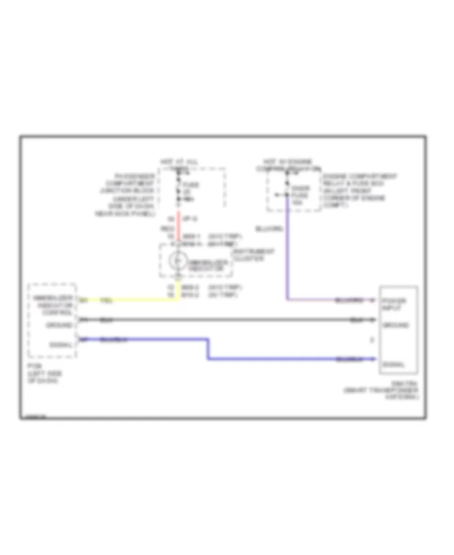
Immobilizer Wiring Diagram for Hyundai Elantra GT 2004
List of elements for Immobilizer Wiring Diagram for Hyundai Elantra GT 2004:
- (under left side of dash, near kick panel)
- (w/o trip) (w/ trip)
- Engine compartment relay & fuse box (in left front corner of engine compt)
- Fuse 15a
- Ground
- Hot at all times
- Hot w/ engine control relay on
- I/p-g
- Immobilizer indicator
- Immobilizer indicator control
- Instrument cluster
- M09-1 m10-1
- M09-2 m10-2
- Passenger compartment junction block
- Pcm (left side of dash)
- Power input
- Red
- Signal
- Smatra (smart transponder antenna)
- Snsr fuse 10a