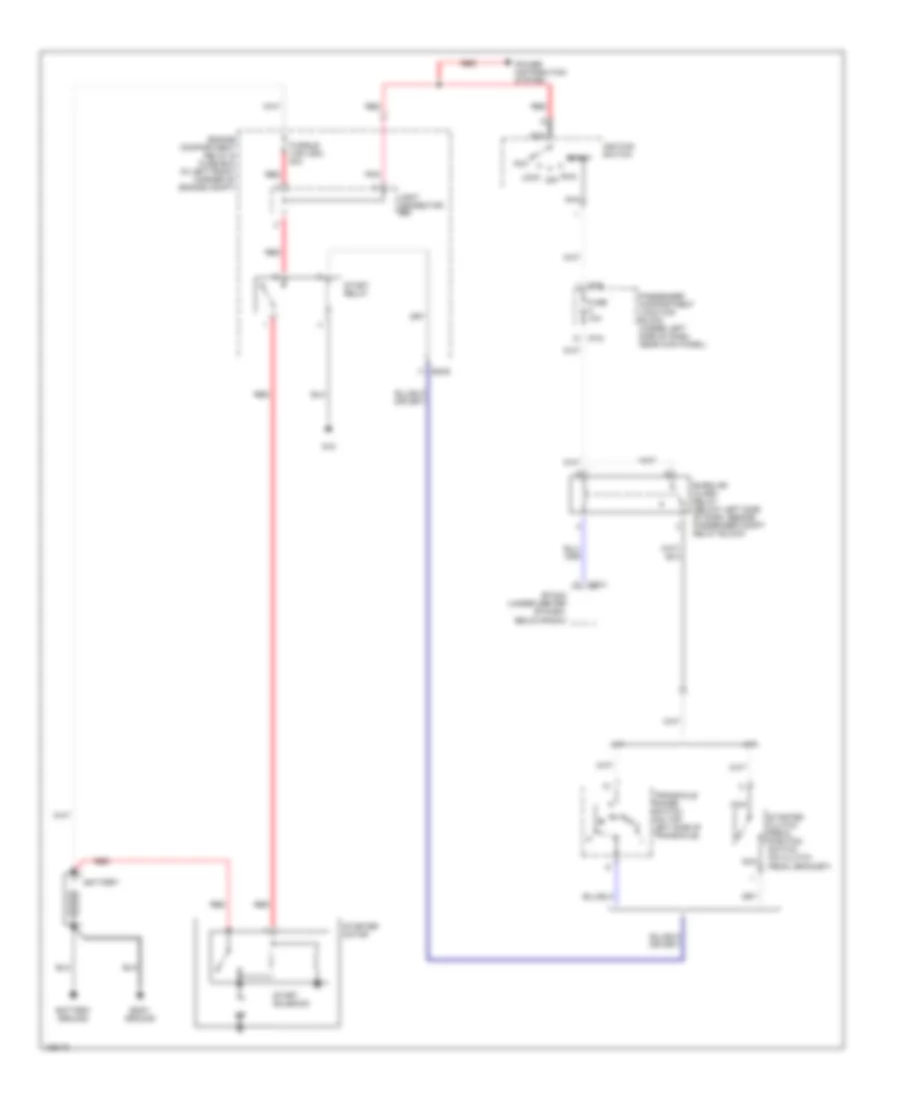
STARTING/CHARGING
Charging Wiring Diagram for Hyundai Elantra GT 2004

List of elements for Charging Wiring Diagram for Hyundai Elantra GT 2004:
- (in left front corner of engine compt) engine compartment relay & fuse box
- (w/ trip)
- (w/o trip)
- Battery
- Battery ground
- Body ground
- Charge indicator
- E20-2
- Fuse 10a
- Fusible link (batt) 120a
- Fusible link (ecu) 20a
- Generator
- Headlights system
- Hot in on or start
- I/p-b
- I/p-h
- Instrument cluster
- M09-1
- M09-2
- M10-1
- Passenger compartment junction block (under left side of dash, near kick panel)
- Pre- excitation resistor
- Red
- Starting circuit
Starting Wiring Diagram for Hyundai Elantra GT 2004
List of elements for Starting Wiring Diagram for Hyundai Elantra GT 2004:
- A/t
- Acc
- Battery
- Battery ground
- Body ground
- Burglar alarm relay (below left side of dash, beside passenger compt relay block)
- Ec05
- Engine compartment relay & fuse box (in left front corner of engine compt)
- Etacm (under center of dash, below radio)
- Fuse 10a
- Fusible link (ign) 40a
- G15
- I/p-e
- I/p-g
- Ignition switch
- Joint connector e55
- Lock
- M/t
- M25-3
- N d
- Nca
- Passenger compartment junction block (under left side of dash, near kick panel)
- Pnk
- Power distribution system
- Red
- Run off
- Start
- Start relay
- Start solenoid
- Starter clutch pedal position switch (on clutch pedal bracket)
- Starter motor
- Transaxle range switch (on top left side of transaxle)