СИСТЕМА ПЕРЕДАЧИ ДАННЫХ
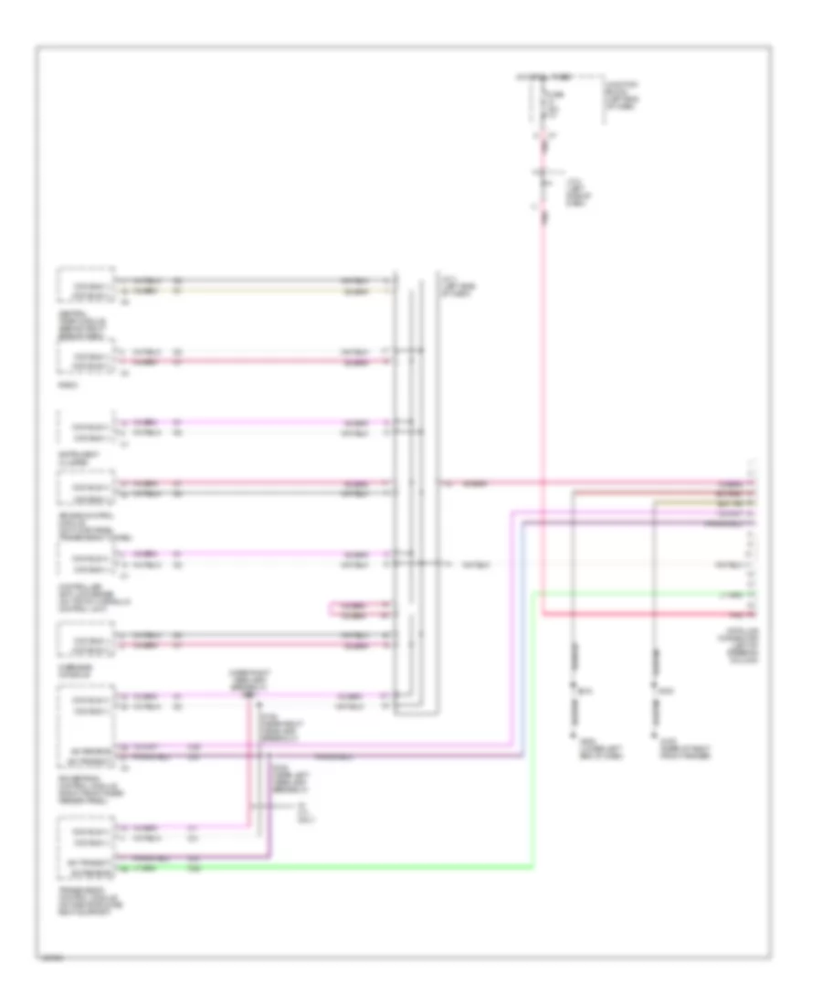
Электросхема компьютерной линии передачи данных CAN для Dodge Durango 2000
Электросхема компьютерной линии передачи данных CAN для Dodge Durango 2000 - Список элементов:
- (near right headlamp breakout) s131
- Air bag control module (on floor panel transmission tunnel)
- Ccd bus (+)
- Ccd bus (-)
- Central timer module (behind right side of dash)
- Controller anti-lock brake (on top of hydraulic control unit)
- D20
- D21
- D22
- Data link connector (left of steering column)
- Fuse 15a
- G105 (rear of right front fender)
- G202 (lower left end of dash)
- Hot at all times
- Instrument cluster
- J/c 3 (left side of dash)
- J/c 4 (left side of dash)
- Junction block (left end of dash)
- Overhead console
- Pnk
- Powertrain control module (right front inner fender panel)
- Radio
- S105
- S125 (near left headlamp breakout)
- S132 (near right headlamp breakout)
- S218
- Sci receive
- Sci transmit
- Transmission control module (on radiator core right support)
- W/ 4.7l only
 Русский