ANTI-LOCK BRAKES
All-Wheel ABS Wiring Diagram for Ford Ranger 1998

List of elements for All-Wheel ABS Wiring Diagram for Ford Ranger 1998:
- (main harn, near breakout to gem)
- (main harn, near breakout to tcs)
- (top center of left fender apron)
- (top center of left fender apron) g104
- 4wabs control module (left side of engine compt)
- 4wd on
- Abs ind
- Abs module fuse 30a red
- Acceleration sensor (left side of engine compt)
- Anti-lock brakes indicator
- Batt
- Bpp sw
- Brake pedal position switch (on pedal support)
- C216
- Data link connector (bottom of dash)
- Engine compartment fuse/ relay box
- Engine controls system
- Fuse 10a
- Fuse 7.5a
- G sw
- G sw 2
- G sw1
- G104
- Gem module, instrument cluster, pcm, speed control assembly
- Ground
- Hot at all times
- Hot in run
- Hot in run or start
- I/p fuse panel
- Ign
- Instrument cluster
- Iso lnk
- Left front wheel speed sensor
- Lf sens
- Pmp fd
- Rear axle sensor (on axle assembly)
- Red
- Red/pnk
- Rf sens
- Right front wheel speed sensor
- Rr sens
- S225
- S228
- S240
- Vss out
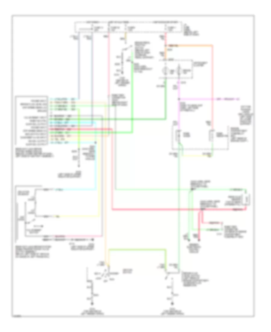
Rear Wheel ABS Wiring Diagram for Ford Ranger 1998
List of elements for Rear Wheel ABS Wiring Diagram for Ford Ranger 1998:
- (main harn, near breakout to i/p fuse panel) s235
- (main harn, near breakout to i/p fuse panel) s236
- (top center of left fender apron)
- 1.2 ohms
- 22k ohms
- 4.0 ohms
- Abs ind
- Acc
- Boo switch input
- Brake fluid level sig
- Brake fluid level switch (left rear of engine compartment, on brake fluid reservoir)
- Brake ind
- Brake pedal position switch (behind left side of dash, on brake pedal support)
- C141
- C215
- C216
- Daytime running lamps (drl) module (left side of lower radiator support)
- Diag/keep alive input
- Diff speed sens (hi)
- Diff speed sens (lo)
- Dump sol output
- Engine compartment fuse/relay box (left rear of engine compt.)
- Fuse 11 7.5a
- Fuse 14 20a
- Fuse 35 10a
- Fuse 9 7.5a
- G104
- G104 (top center of left fender apron)
- G108 (left side of upper radiator support)
- Generic electronic control module
- Gnd
- Ground
- Hot at all times
- Hot in run
- Hot in run or start
- I/p fuse panel (behind left side of dash)
- Ignition switch
- Instrument cluster
- Iso sol output
- Isolation solenoid
- Lock
- Nca
- Off
- Power input
- Rabs diode
- Rabs ind ctrl
- Rabs resistor
- Rabs test connector (c244) (behind right side of dash)
- Rabs test connector (on rear of engine compartment fuse/relay box)
- Rear anti-lock brake system (rabs) module (behind lower center of dash, left side of ashtray assembly)
- Rear anti-lock brake system (rabs) proportioning valve switch assembly (below left side of vehicle, on inside of left frame rail)
- Rear axle sensor (top of rear differential)
- Red
- Red/ pnk
- Red/pnk
- Run
- S118
- S120 (dash to headlamp harn, left side of firewall)
- S131
- S204 (main harn, near breakout to rabs module)
- S205
- S228
- S228 (main harn, near breakout to tcs)
- S240
- S244
- Start
- Valve reset input
- Valve reset switch