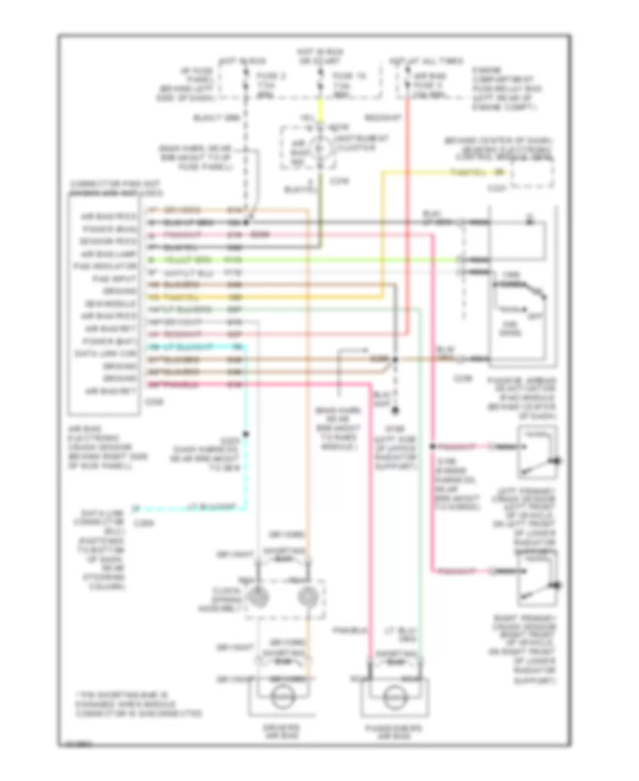
SUPPLEMENTAL RESTRAINTS
Supplemental Restraint Wiring Diagram for Ford Ranger 1998
List of elements for Supplemental Restraint Wiring Diagram for Ford Ranger 1998:
- (behind center of dash) generic electronic control module (gem)
- (dlc) (fastened to bottom of dash, near steering column)
- (engine harness, near breakout to horns)
- (left side of upper radiator support)
- (main harn, near breakout to rabs module)
- (main harn, near breakout to i/p fuse panel)
- * pin shorting bar is engaged when module connector is disconnected
- Air bag electronic crash sensor (behind right side of kick panel)
- Air bag feed
- Air bag fuse 5 10a mini
- Air bag ind
- Air bag lamp
- Air bag ret
- C216
- C221
- C250
- C256
- Clock- spring assembly
- Connector pins not shown are not used
- Data link con
- Data link connector c209
- Driver's air bag
- Engine compartment fuse/relay box (left rear of engine compt)
- Fuse 15 7.5a mini
- Fuse 2 7.5a mini
- G108
- Gem module
- Ground
- Hot at all times
- Hot in run
- Hot in run or start
- I/p fuse panel (behind left side of dash)
- Instrument cluster
- Left primary crash sensor (left front of vehicle, on left front of lower radiator support)
- Nca
- Off
- Ohms
- Pad indicator
- Pad input
- Passenger's air bag
- Passive airbag deactivation (pad) module (behind center of dash)
- Power (bat)
- Power (run)
- Right primary crash sensor (right front of vehicle, on right front of lower radiator
- S156
- S205
- S225 dash harness, near breakout to gem
- S250
- Sensor feed
- Shorting bar
- Support)
 English