ENGINE PERFORMANCE
2.5L
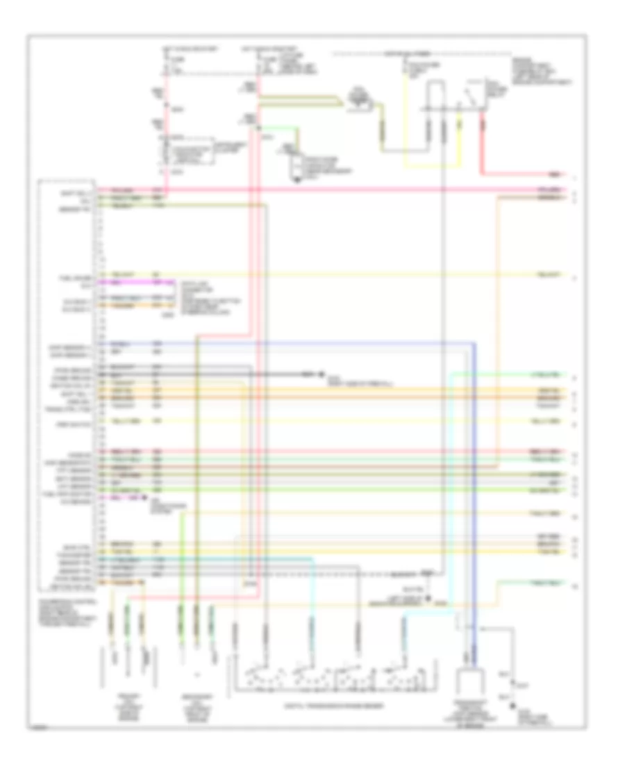
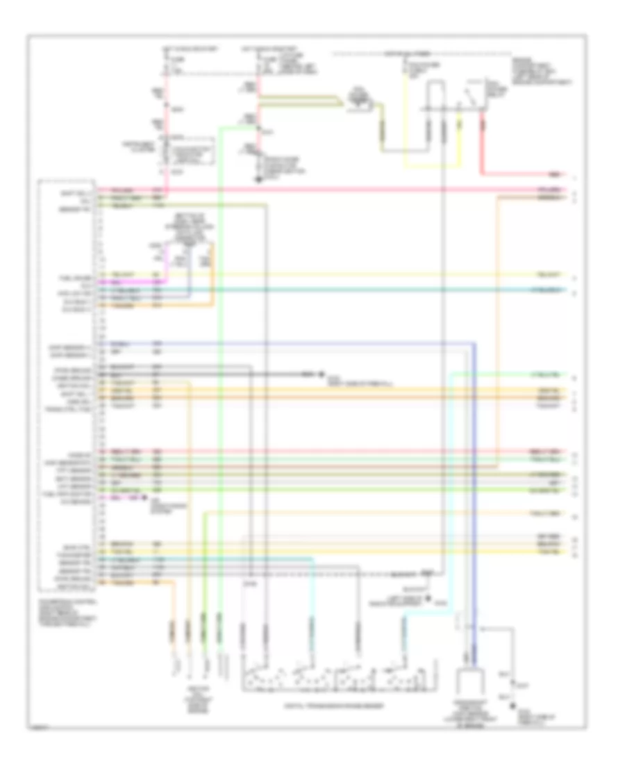
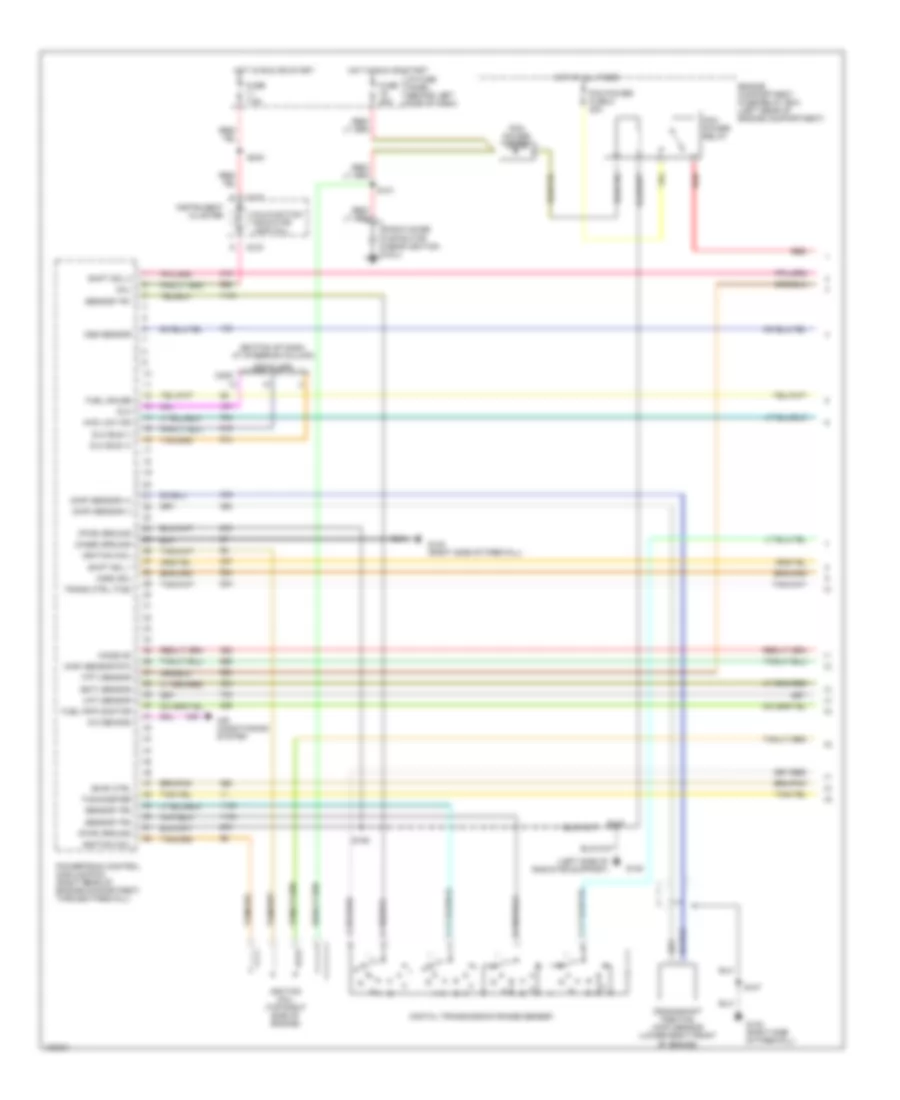
2.5L, Engine Performance Wiring Diagrams (1 of 4) for Ford Ranger 1998
 https://portal-diagnostov.com/license.html
Automotive Electricians Portal FZCO
Automotive Electricians Portal FZCO
https://portal-diagnostov.com/license.html
https://portal-diagnostov.com/license.html
Automotive Electricians Portal FZCO
Automotive Electricians Portal FZCO
List of elements for 2.5L, Engine Performance Wiring Diagrams (1 of 4) for Ford Ranger 1998:
- (case) ground
- (ckp) sensor (+)
- (ckp) sensor (-)
- (css) sol
- (ect) sensor
- (evr) ctrl
- (ho2s) #2
- (iat) sensor
- (left side of radiator support)
- (maf) sensor rtn
- (mil)
- (psp) switch
- (pwr) ground
- (tft) sensor
- A/c demand
- Air conditioning system
- C209
- C215
- Crankshaft position (ckp) sensor (lower right front of engine)
- Data link connector (dlc) (fastened to bottom of dash near steering column)
- Digital transmission range sensor
- Dlc
- Dlc bus (+)
- Dlc bus (-)
- Engine compartment fuse/relay box (left rear of engine compartment)
- Fuel gauge
- Fuel pmp monitor
- Fuse 25a
- Fuse 7.5a
- G108
- G123 (right side of firewall)
- Hot at all times
- Hot in run or start
- I/p fuse panel (behind left side of dash)
- Ignition coil #1
- Ignition coil #2
- Instrument cluster
- Malfunction indicator lamp (mil)
- Pcm power diode
- Pcm power fuse 8 30a
- Pcm power relay
- Powertrain control module (pcm) (right rear of engine compartment, through firewall)
- Primary coil (top right side of engine)
- Radio noise capacitor (near secondary coil)
- Red
- S101
- S106
- S107
- S118
- S240
- Secondary coil (top right front of engine)
- Sensor tr1
- Sensor tr2
- Sensor tr4
- Shift sol 1
- Shift sol 2
- Tachometer
- Trans ctrl (tcs)
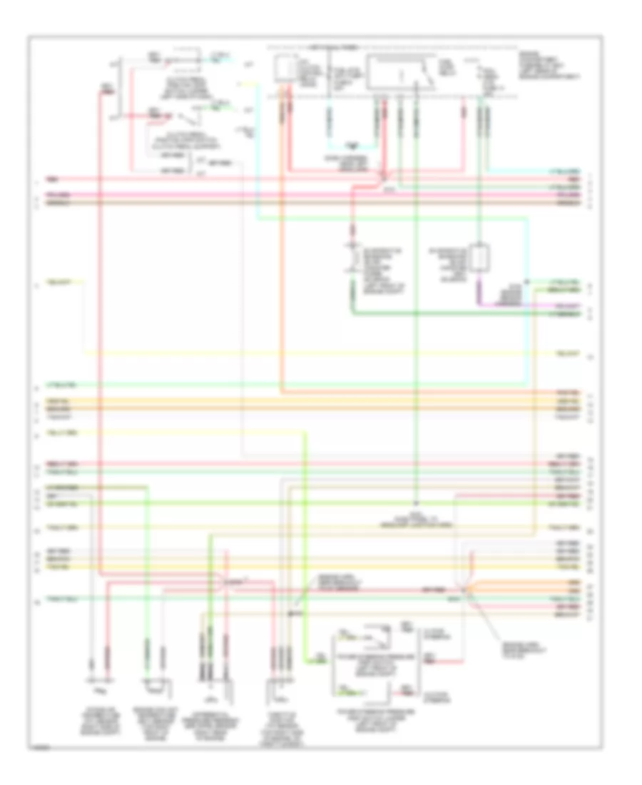
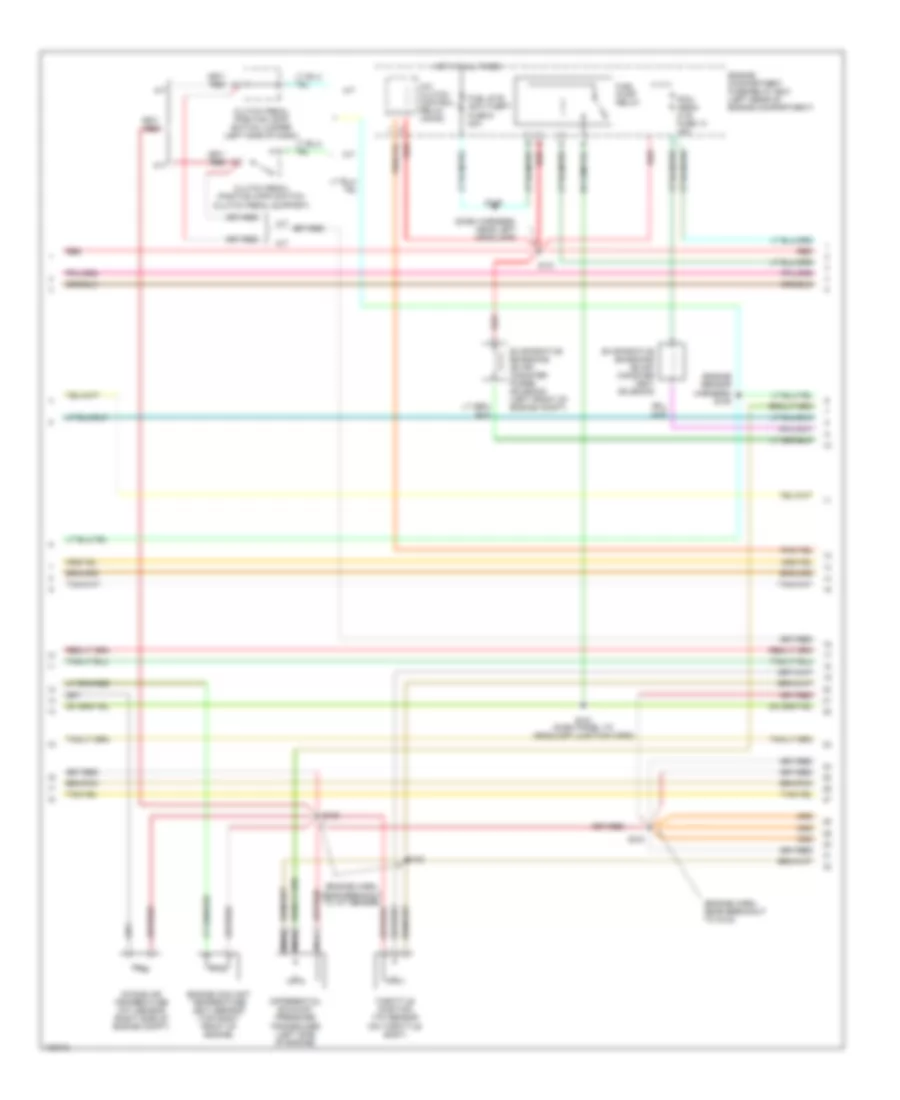
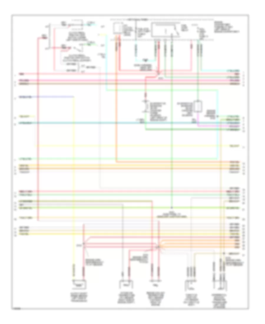
2.5L, Engine Performance Wiring Diagrams (2 of 4) for Ford Ranger 1998
 https://portal-diagnostov.com/license.html
Automotive Electricians Portal FZCO
Automotive Electricians Portal FZCO
https://portal-diagnostov.com/license.html
https://portal-diagnostov.com/license.html
Automotive Electricians Portal FZCO
Automotive Electricians Portal FZCOList of elements for 2.5L, Engine Performance Wiring Diagrams (2 of 4) for Ford Ranger 1998:
- (dash harness, near left headlamp)
- (engine harn, near breakout to g123)
- (engine harn, near breakout to iat sensor)
- A/c clutch control relay (accr)
- A/t
- Clutch pedal position (cpp) switch (clutch pedal support)
- Clutch pedal position (cpp) switch jumper (left side of dash)
- Differential pressure feedback egr (dpfe) sensor (right rear of engine)
- Engine compartment fuse/relay box (left rear of engine compartment)
- Engine coolant temperature (ect) sensor (top right front of engine)
- Evaporative emissions (evap) canister purge solenoid (left front of engine compt)
- Evaporative emissions (evap) canister vent solenoid
- Fuel pump relay
- Fuel sys/ anti-theft fuse 9 20a
- Hot at all times
- Intake air temperature (iat) sensor (right side of engine compt)
- M/t
- Nca
- Pcm/ hego/ cvs fuse 13 15a
- Power steering pressure (psp) switch (left front of engine compt)
- Power steering pressure (psp) switch jumper (left front of engine compt)
- Red
- S100
- S102
- S103
- S108 (engine sensor harness)
- S116
- S121
- S151 (dash panel to headlamp junction harn)
- Throttle position (tp) sensor (top right side of engine, on throttle body)
- W/ pwr steering
- W/o pwr steering
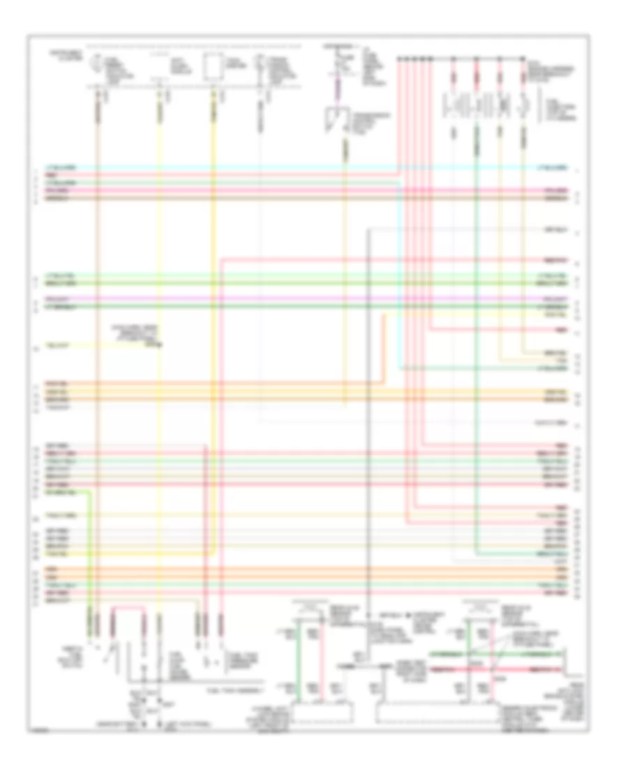
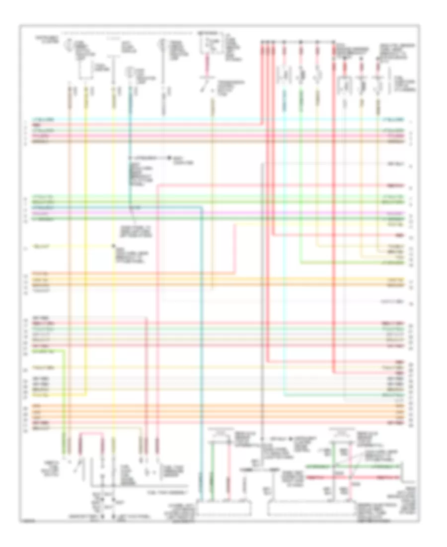
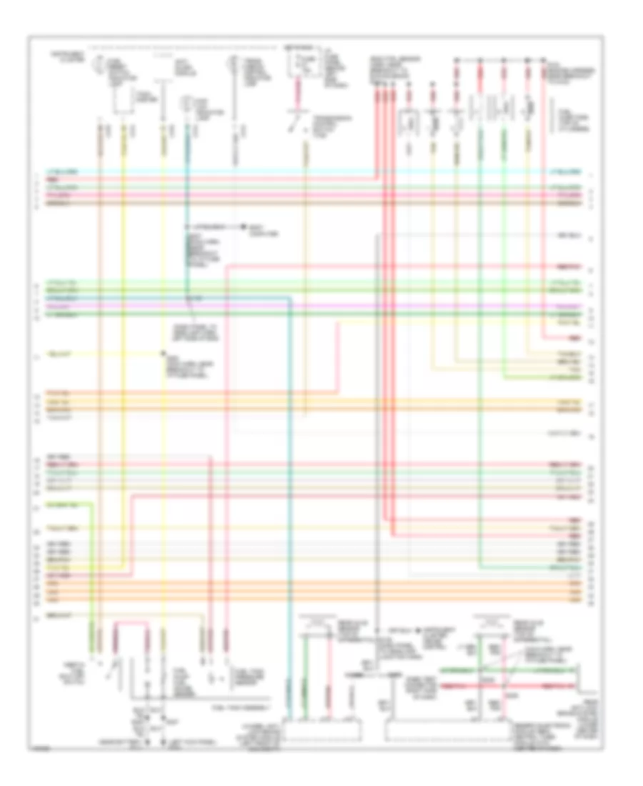
2.5L, Engine Performance Wiring Diagrams (3 of 4) for Ford Ranger 1998
 https://portal-diagnostov.com/license.html
Automotive Electricians Portal FZCO
Automotive Electricians Portal FZCO
https://portal-diagnostov.com/license.html
https://portal-diagnostov.com/license.html
Automotive Electricians Portal FZCO
Automotive Electricians Portal FZCOList of elements for 2.5L, Engine Performance Wiring Diagrams (3 of 4) for Ford Ranger 1998:
- (left kick panel) g200
- (main harn, near breakout to i/p fuse panel)
- (main harn, near breakout to i/p fuse panel) s253
- (near battery) g111
- (right side of dash)
- 4-wheel anti- lock brake system module (left front of eng compt)
- 4wabs
- Anti- slosh module
- C214
- C215
- Fuel injectors (top of cylinders)
- Fuel pump/ fuel gauge sender
- Fuel reset switch indicator lamp
- Fuel tank assembly
- Fuel tank pressure sensor
- Fuse 15a
- Generic electronic module (gem)/ central timer module (ctm) (center of dash)
- Hot in run
- I/p fuse panel (behind left side of dash)
- Inertia fuel shut-off switch
- Instrument cluster
- Instrument cluster, cruise control
- Rabs
- Rabs test connector red/pnk
- Rear anti-lock brake system module (lower center of dash)
- Rear axle sensor (top of differential)
- Red
- Red/ pnk
- Red/pnk
- S104 (engine harness, near breakout to g123)
- S139 (dash panel to headlamp junction harn)
- S205
- S235
- S236
- S307
- Tach- ometer
- Tan
- Trans- mission control indicator lamp
- Transmission control switch (tcs)
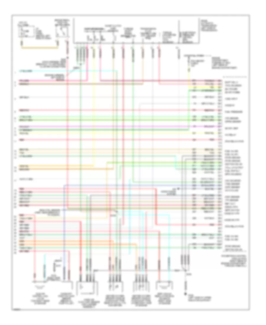
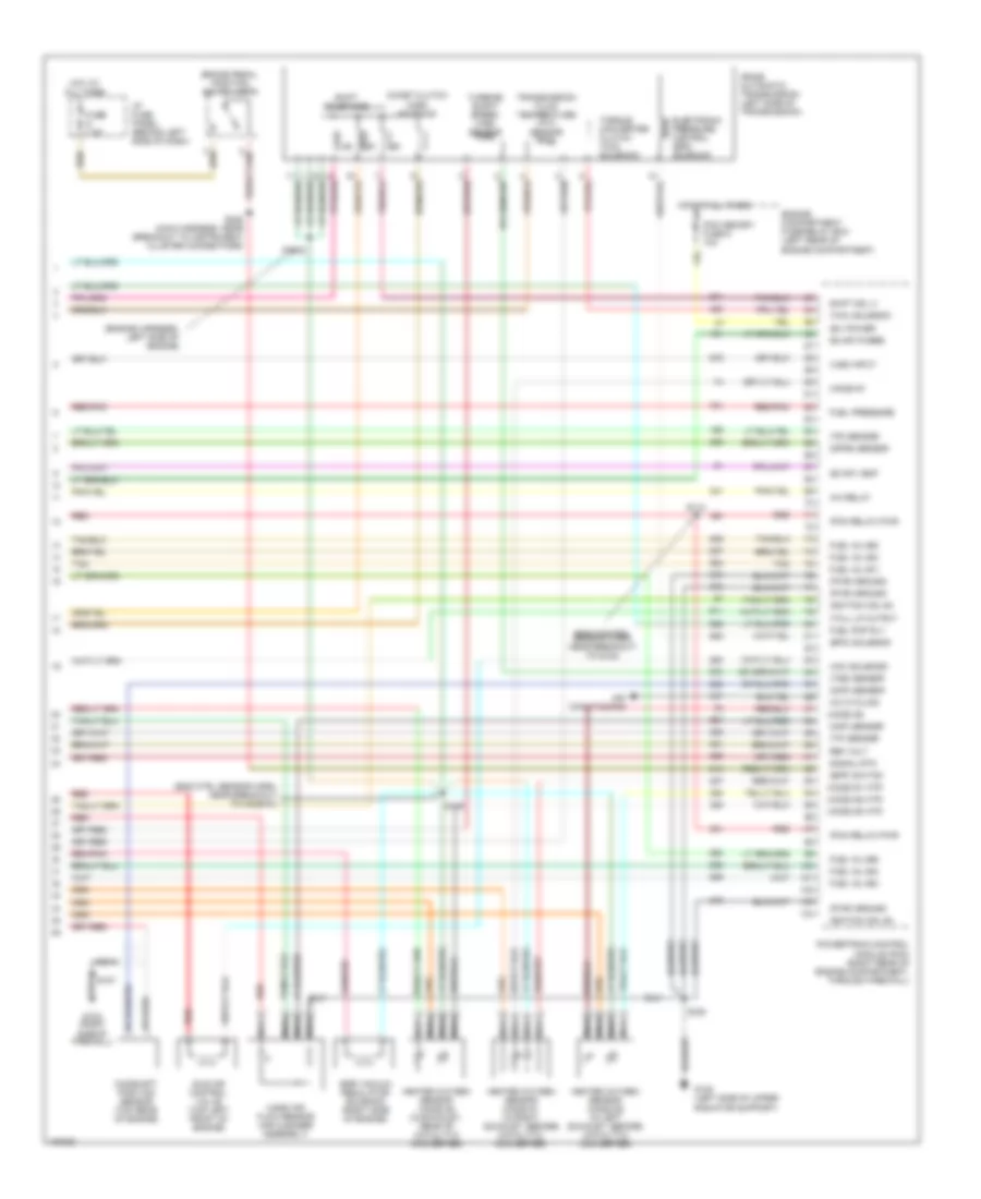
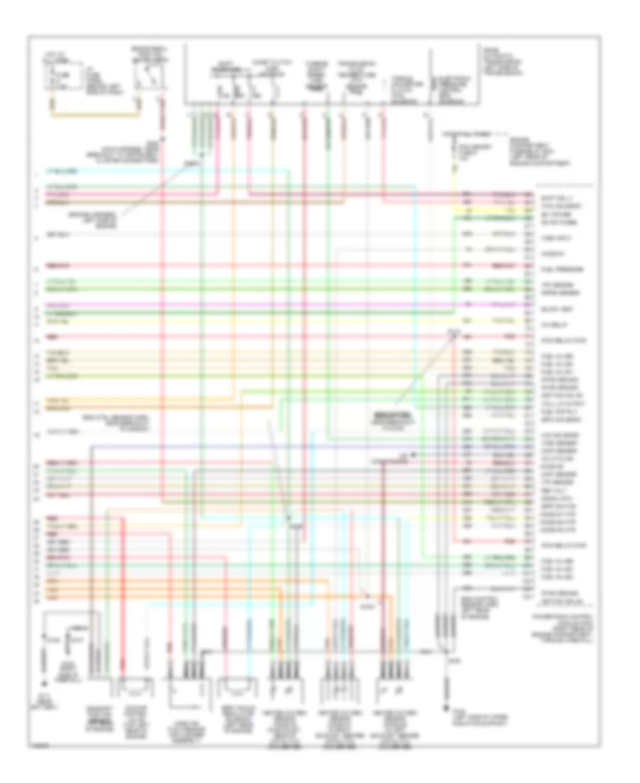
2.5L, Engine Performance Wiring Diagrams (4 of 4) for Ford Ranger 1998
 https://portal-diagnostov.com/license.html
Automotive Electricians Portal FZCO
Automotive Electricians Portal FZCO
https://portal-diagnostov.com/license.html
https://portal-diagnostov.com/license.html
Automotive Electricians Portal FZCO
Automotive Electricians Portal FZCOList of elements for 2.5L, Engine Performance Wiring Diagrams (4 of 4) for Ford Ranger 1998:
- (b+) power
- (bpp) switch
- (cmp) sensor
- (dpfe) sensor
- (eng ctrl sensor harn, near breakout to ho2s #1)
- (engine harness, left side of engine)
- (epc) solenoid
- (evap) purge
- (evap) vent
- (ho2s) #1
- (ho2s) #1 htr
- (ho2s) #2 htr
- (iac) solenoid
- (maf) sensor
- (pcm relay) pwr
- (pwr) ground
- (tcc) solenoid
- (tcil) lp output
- (tp) sensor
- (tr) sensor
- (tss) sensor
- (vss) input
- 4r44e automatic transmission (left side of transmission)
- A/c cycling
- A/c relay
- Air conditioning system
- Brake pedal position switch (bpp)
- Camshaft position (cmp) sensor (behind oil pump pulley)
- Coast clutch (css) solenoid
- Egr vacuum regulator (evr) solenoid (right side of engine)
- Electronic pressure control (epc) solenoid
- Engine compartment fuse/relay box (left rear of engine compartment)
- Fuel inj (#1)
- Fuel inj (#2)
- Fuel inj (#3)
- Fuel inj (#4)
- Fuel pmp rly
- Fuel pressure
- Fuse 7.5a
- G108 (left side of upper radiator support)
- G123 (right side of firewall)
- Heated oxygen sensor (ho2s) #1 (in exhaust pipe, lower right side of engine)
- Heated oxygen sensor (ho2s) #2 (in exhaust pipe, rear of catalytic converter)
- Hot at all times
- I/p fuse panel (behind left side of dash)
- Idle air control (iac) valve (top right rear of engine)
- Ignition coil #3
- Ignition coil #4
- Mass air flow (maf) sensor (air cleaner assembly)
- Nca
- Pcm memory fuse 6 10a
- Powertrain control module (pcm) (right rear of engine compartment, through firewall)
- Red
- Red/pnk
- Ref volt
- S1002
- S106
- S107
- S109
- S228 (main harness, near breakout to instrument cluster connectors)
- Shift sol 3
- Shift solenoids
- Signal rtn
- Tan
- Torque converter clutch (tcc) solenoid
- Transmission fluid temperature (tft) sensor
- Turbine shaft speed sensor (tss)
3.0L
3.0L, Engine Performance Wiring Diagrams (1 of 4) for Ford Ranger 1998
 https://portal-diagnostov.com/license.html
Automotive Electricians Portal FZCO
Automotive Electricians Portal FZCO
https://portal-diagnostov.com/license.html
https://portal-diagnostov.com/license.html
Automotive Electricians Portal FZCO
Automotive Electricians Portal FZCOList of elements for 3.0L, Engine Performance Wiring Diagrams (1 of 4) for Ford Ranger 1998:
- (bottom of dash, near steering column) data link connector (dlc)
- (case) ground
- (ckp) sensor (+)
- (ckp) sensor (-)
- (css) sol
- (ect) sensor
- (evr) ctrl
- (ho2s) #3
- (iat) sensor
- (left side of radiator support)
- (maf) sensor rtn
- (mil)
- (pwr) ground
- (tft) sensor
- 4wd low ind
- A/c demand
- Air conditioning system
- C209
- C215
- Crankshaft position (ckp) sensor (lower right front of engine)
- Digital transmission range sensor
- Dlc
- Dlc bus (+)
- Dlc bus (-)
- Engine compartment fuse/relay box (left rear of engine compartment)
- Fuel gauge
- Fuel pmp monitor
- Fuse 25a
- Fuse 7.5a
- G108
- G123 (right side of firewall)
- Hot at all times
- Hot in run or start
- I/p fuse panel (behind left side of dash)
- Ignition coil
- Ignition coil (top right side of engine)
- Instrument cluster
- Malfunction indicator lamp (mil)
- Pcm power diode
- Pcm power fuse 8 30a
- Pcm power relay
- Powertrain control module (pcm) (right rear of engine compartment, through firewall)
- Radio noise capacitor (near ignition coil)
- Red
- S101
- S106
- S107
- S118
- S240
- Sensor tr1
- Sensor tr2
- Sensor tr4
- Shift sol 1
- Shift sol 2
- Tachometer
- Trans ctrl (tcs)
3.0L, Engine Performance Wiring Diagrams (2 of 4) for Ford Ranger 1998
 https://portal-diagnostov.com/license.html
Automotive Electricians Portal FZCO
Automotive Electricians Portal FZCO
https://portal-diagnostov.com/license.html
https://portal-diagnostov.com/license.html
Automotive Electricians Portal FZCO
Automotive Electricians Portal FZCOList of elements for 3.0L, Engine Performance Wiring Diagrams (2 of 4) for Ford Ranger 1998:
- (dash harness, near left headlamp)
- (engine harn, near breakout to g123)
- (engine harn, near breakout to iat sensor)
- (engine sensor harness) s108
- A/c clutch control relay (accr)
- A/t
- Clutch pedal position (cpp) switch (clutch pedal support)
- Clutch pedal position (cpp) switch jumper (left side of dash)
- Differential exhaust pressure transducer (left side of engine)
- Engine compartment fuse/relay box (left rear of engine compartment)
- Engine coolant temperature (ect) sensor (top right front of engine)
- Evaporative emissions (evap) canister purge solenoid (left front of engine compt)
- Evaporative emissions (evap) canister vent solenoid
- Fuel pump relay
- Fuel sys/ anti-theft fuse 9 20a
- Hot at all times
- Intake air temperature (iat) sensor (right side of engine compt)
- M/t
- Nca
- Pcm/ hego/ cvs fuse 13 15a
- Red
- S100
- S102
- S103
- S116
- S121
- S151 (dash panel to headlamp junction harn)
- Throttle position (tp) sensor (on throttle body)
3.0L, Engine Performance Wiring Diagrams (3 of 4) for Ford Ranger 1998
 https://portal-diagnostov.com/license.html
Automotive Electricians Portal FZCO
Automotive Electricians Portal FZCO
https://portal-diagnostov.com/license.html
https://portal-diagnostov.com/license.html
Automotive Electricians Portal FZCO
Automotive Electricians Portal FZCOList of elements for 3.0L, Engine Performance Wiring Diagrams (3 of 4) for Ford Ranger 1998:
- (dash panel to headlamp harn, left side of eng)
- (eng ctrl sensor harn, near breakout to evr solenoid) s113 red
- (left kick panel) g200
- (main harn, near breakout to i/p fuse panel)
- (near battery) g111
- (right side of dash)
- 4-wheel anti- lock brake system module (left front of eng compt)
- 4wabs
- 4wd low indicator lamp
- Anti- slosh module
- Body computer
- C214
- C215
- Fuel injectors (top of cylinders)
- Fuel pump/ fuel gauge sender
- Fuel reset switch indicator lamp
- Fuel tank assembly
- Fuel tank pressure sensor
- Fuse 15a
- Generic electronic module (gem)/ central timer module (ctm) (center of dash)
- Hot in run
- I/p fuse panel (behind left side of dash)
- Inertia fuel shut-off switch
- Instrument cluster
- Instrument cluster, cruise control
- Rabs
- Rabs test connector red/pnk
- Rear anti-lock brake system module (lower center of dash)
- Rear axle sensor (top of differential)
- Red
- Red/ pnk
- Red/pnk
- S104 red (engine harness, near breakout to g123)
- S139 (dash panel to headlamp junction harn)
- S152
- S205
- S235
- S236
- S253 (main harn, near breakout to i/p fuse panel)
- S307
- Tach- ometer
- Tan
- Trans- mission control indicator lamp
- Transmission control switch (tcs)
3.0L, Engine Performance Wiring Diagrams (4 of 4) for Ford Ranger 1998
 https://portal-diagnostov.com/license.html
Automotive Electricians Portal FZCO
Automotive Electricians Portal FZCO
https://portal-diagnostov.com/license.html
https://portal-diagnostov.com/license.html
Automotive Electricians Portal FZCO
Automotive Electricians Portal FZCOList of elements for 3.0L, Engine Performance Wiring Diagrams (4 of 4) for Ford Ranger 1998:
- (b+) power
- (bpp) switch
- (cmp) sensor
- (dpfe) sensor
- (eng control sensor harn, near breakout to g123)
- (eng ctrl sensor harn, near breakout to ho2s #1)
- (engine harness, left side of engine)
- (epc) solenoid
- (evap) purge
- (evap) vent
- (ho2s) #1
- (ho2s) #1 htr
- (ho2s) #2
- (ho2s) #2 htr
- (ho2s) #3 htr
- (iac) solenoid
- (maf) sensor
- (pcm relay) pwr
- (pwr) ground
- (tcc) solenoid
- (tcil) lp output
- (tp) sensor
- (tr) sensor
- (tss) sensor
- (vss) input
- 4r44e automatic transmission (left side of transmission)
- A/c cycling
- A/c relay
- Air conditioning
- Brake pedal position switch (bpp)
- Camshaft position sensor (top rear of engine)
- Coast clutch (css) solenoid
- Egr vacuum regulator solenoid (right side of engine)
- Electronic pressure control (epc) solenoid
- Engine compartment fuse/relay box (left rear of engine compartment)
- Fuel inj (#1)
- Fuel inj (#2)
- Fuel inj (#3)
- Fuel inj (#4)
- Fuel inj (#5)
- Fuel inj (#6)
- Fuel pmp rly
- Fuel pressure
- Fuse 7.5a
- G108 (left side of upper radiator support)
- G123 (right side of firewall)
- Heated oxygen sensor (ho2s) #1 (in right exhaust, before catalytic converter)
- Heated oxygen sensor (ho2s) #2 (in left exhaust, before catalytic converter)
- Heated oxygen sensor (ho2s) #3 (in exhaust, rear of catalytic converter)
- Hot at all times
- I/p fuse panel (behind left side of dash)
- Idle air control valve (top left front of engine)
- Ignition coil #3
- Ignition coil #4
- Mass air flow sensor (air cleaner assembly)
- Nca
- Pcm memory fuse 6 10a
- Powertrain control module (pcm) (right rear of engine compartment, through firewall)
- Red
- Red/pnk
- Ref volt
- S1002
- S106
- S107
- S109
- S112
- S228 (main harness, near breakout to instrument cluster connectors)
- Shift sol 3
- Shift solenoids
- Signal rtn
- Tan
- Torque converter clutch (tcc) solenoid
- Transmission fluid temperature (tft) sensor
- Turbine shaft speed (tss) sensor
4.0L
4.0L, Engine Performance Wiring Diagrams (1 of 4) for Ford Ranger 1998
 https://portal-diagnostov.com/license.html
Automotive Electricians Portal FZCO
Automotive Electricians Portal FZCO
https://portal-diagnostov.com/license.html
https://portal-diagnostov.com/license.html
Automotive Electricians Portal FZCO
Automotive Electricians Portal FZCOList of elements for 4.0L, Engine Performance Wiring Diagrams (1 of 4) for Ford Ranger 1998:
- (bottom of dash, at steering column)
- (case) ground
- (ckp) sensor (+)
- (ckp) sensor (-)
- (css) sol
- (ect) sensor
- (evr) ctrl
- (ho2s) #3
- (iat) sensor
- (left side of radiator support)
- (maf) sensor rtn
- (mil)
- (pwr) ground
- (tft) sensor
- 4wd low ind
- A/c demand
- Air conditioning system
- C209
- C215
- Crankshaft position (ckp) sensor (lower right front of engine)
- Data link connector (dlc)
- Digital transmission range sensor
- Dlc
- Dlc bus (+)
- Dlc bus (-)
- Engine compartment fuse/relay box (left rear of engine compartment)
- Fuel gauge
- Fuel pmp monitor
- Fuse 25a
- Fuse 7.5a
- G108
- G123 (right side of firewall)
- Hot at all times
- Hot in run or start
- I/p fuse panel (behind left side of dash)
- Ignition coil
- Ignition coil (top right side of engine)
- Instrument cluster
- Malfunction indicator lamp (mil)
- Oss sensor
- Pcm power diode
- Pcm power fuse 8 30a
- Pcm power relay
- Powertrain control module (pcm) (right rear of engine compartment, through firewall)
- Radio noise capacitor (near ignition coil)
- Red
- S101
- S106
- S107
- S118
- S240
- Sensor tr1
- Sensor tr2
- Sensor tr4
- Shift sol 1
- Shift sol 2
- Tachometer
- Trans ctrl (tcs)
4.0L, Engine Performance Wiring Diagrams (2 of 4) for Ford Ranger 1998
 https://portal-diagnostov.com/license.html
Automotive Electricians Portal FZCO
Automotive Electricians Portal FZCO
https://portal-diagnostov.com/license.html
https://portal-diagnostov.com/license.html
Automotive Electricians Portal FZCO
Automotive Electricians Portal FZCOList of elements for 4.0L, Engine Performance Wiring Diagrams (2 of 4) for Ford Ranger 1998:
- (dash harness, near left headlamp)
- (engine harn, near breakout to iat sensor)
- (engine sensor harness) s108
- A/c clutch control relay (accr)
- A/t
- Clutch pedal position (cpp) switch (clutch pedal support)
- Clutch pedal position (cpp) switch jumper (left side of dash)
- Differential exhaust pressure transducer (left side of engine)
- Engine compartment fuse/relay box (left rear of engine compartment)
- Engine coolant temperature (ect) sensor (top right front of engine)
- Evaporative emissions (evap) canister purge solenoid (left front of engine compt)
- Evaporative emissions (evap) canister vent solenoid
- Fuel pump relay
- Fuel sys/ anti-theft fuse 9 20a
- Hot at all times
- Intake air temperature (iat) sensor (right side of engine compt.)
- M/t
- Nca
- Output shaft speed sensor (left side of transmission)
- Pcm/ hego/ cvs fuse 13 15a
- Red
- S100 (engine harn, near breakout to iat sensor)
- S102
- S103 (engine harn, near breakout to g123)
- S116
- S121
- S151 (dash panel to headlamp junction harn)
- Throttle position (tp) sensor (on throttle body)
4.0L, Engine Performance Wiring Diagrams (3 of 4) for Ford Ranger 1998
 https://portal-diagnostov.com/license.html
Automotive Electricians Portal FZCO
Automotive Electricians Portal FZCO
https://portal-diagnostov.com/license.html
https://portal-diagnostov.com/license.html
Automotive Electricians Portal FZCO
Automotive Electricians Portal FZCOList of elements for 4.0L, Engine Performance Wiring Diagrams (3 of 4) for Ford Ranger 1998:
- (dash panel to headlamp harn, left side of eng)
- (eng ctrl sensor harn, near breakout to evr solenoid) s113
- (left kick panel) g200
- (main harn, near breakout to i/p fuse panel)
- (near battery) g111
- (right side of dash)
- 4-wheel anti- lock brake system module (left front of eng compt)
- 4wabs
- 4wd low indicator lamp
- Anti- slosh module
- Body computer
- C214
- C215
- Fuel injectors (top of cylinders)
- Fuel pump/ fuel gauge sender
- Fuel reset switch indicator lamp
- Fuel tank assembly
- Fuel tank pressure sensor
- Fuse 15a
- Generic electronic module (gem)/ central timer module (ctm) (center of dash)
- Hot in run
- I/p fuse panel (behind left side of dash)
- Inertia fuel shut-off switch
- Instrument cluster
- Instrument cluster, cruise control
- Rabs
- Rabs test connector red/pnk
- Rear anti-lock brake system module (lower center of dash)
- Rear axle sensor (top of differential)
- Red
- Red/ pnk
- Red/pnk
- S104 (engine harness, near breakout to g123)
- S139 (dash panel to headlamp junction harn)
- S152
- S205
- S235
- S236
- S253 (main harn, near breakout to i/p fuse panel)
- S307
- Tach- ometer
- Tan
- Trans- mission control indicator lamp
- Transmission control switch (tcs)
4.0L, Engine Performance Wiring Diagrams (4 of 4) for Ford Ranger 1998
 https://portal-diagnostov.com/license.html
Automotive Electricians Portal FZCO
Automotive Electricians Portal FZCO
https://portal-diagnostov.com/license.html
https://portal-diagnostov.com/license.html
Automotive Electricians Portal FZCO
Automotive Electricians Portal FZCOList of elements for 4.0L, Engine Performance Wiring Diagrams (4 of 4) for Ford Ranger 1998:
- (b+) power
- (bpp) switch
- (cmp) sensor
- (dpfe) sensor
- (eng control sensor harn, left rear of engine)
- (eng control sensor harn, near breakout to g123)
- (eng ctrl sensor harn, near breakout to ho2s #1)
- (engine harness, left side of engine)
- (epc) solenoid
- (evap) purge
- (evap) vent
- (ho2s) #1
- (ho2s) #1 htr
- (ho2s) #2
- (ho2s) #2 htr
- (ho2s) #3 htr
- (iac) solenoid
- (maf) sensor
- (pcm relay) pwr
- (pwr) ground
- (tcc) solenoid
- (tcil) lp output
- (tp) sensor
- (tr) sensor
- (tss) sensor
- (vss) input
- 4r44e automatic transmission (left side of transmission)
- A/c cycling
- A/c relay
- Air conditioning
- Brake pedal position switch (bpp)
- Camshaft position sensor (top rear of engine)
- Coast clutch (css) solenoid
- Egr vacuum regulator solenoid (left rear of engine)
- Electronic pressure control (epc) solenoid
- Engine compartment fuse/relay box (left rear of engine compartment)
- Fuel inj (#1)
- Fuel inj (#2)
- Fuel inj (#3)
- Fuel inj (#4)
- Fuel inj (#5)
- Fuel inj (#6)
- Fuel pmp rly
- Fuel pressure
- Fuse 7.5a
- G108 (left side of upper radiator support)
- G111 (near battery)
- G123 (right side of firewall)
- Heated oxygen sensor (ho2s) #1 (in right exhaust, before catalytic converter)
- Heated oxygen sensor (ho2s) #2 (in left exhaust, before catalytic converter)
- Heated oxygen sensor (ho2s) #3 (in exhaust, rear of catalytic converter)
- Hot at all times
- I/p fuse panel (behind left side of dash)
- Idle air control valve (top left rear of engine)
- Ignition coil #3
- Ignition coil #4
- Mass air flow sensor (air cleaner assembly)
- Nca
- Pcm memory fuse 6 10a
- Powertrain control module (pcm) (right rear of engine compartment, through firewall)
- Red
- Red/pnk
- Ref volt
- S1001
- S1002
- S106
- S107
- S109
- S112
- S228 (main harness, near breakout to instrument cluster connectors)
- Shift sol 3
- Shift solenoids
- Signal rtn
- Tan
- Torque converter clutch (tcc) solenoid
- Transmission fluid temperature (tft) sensor
- Turbine shaft speed (tss) sensor

 Čeština
 Dansk
Dansk Deutsch
 Ελληνικά
 English
 English
 Español
 Suomi
Suomi Français
 Français
 עברית
עברית Hrvatski
 Magyar
 Italiano
 日本語
日本語 Nederlands
 Polski
 Português
 Português
 Română
 Русский
 Slovenčina
 Slovenščina
 Svenska
 Türkçe
 中文 (中国)
