ANTI-THEFT
Forced Entry Wiring Diagram for Hyundai Elantra GT 2004
 https://portal-diagnostov.com/license.html
Automotive Electricians Portal FZCO
Automotive Electricians Portal FZCO
https://portal-diagnostov.com/license.html
https://portal-diagnostov.com/license.html
Automotive Electricians Portal FZCO
Automotive Electricians Portal FZCO
List of elements for Forced Entry Wiring Diagram for Hyundai Elantra GT 2004:
- (behind center of dash) g11
- (left rear of engine compt) siren
- (rear of respective door)
- (under left side of dash, beside passenger compt junction block) passenger compartment relay box
- 4 door
- 5 door
- B/alarm rly cntrl
- Burglar alarm relay (below left side of dash, beside passenger compt relay block)
- Code save
- Dl rly cntrl (lk)
- Dl rly cntrl (unlk)
- Door locks system
- Door sw (all)
- Driver door key
- Driver door key lock/ unlock switch
- Driver door unlock relay
- Ec06
- Ecu fuse 10a
- Engine compartment relay & fuse box (in left front corner of engine compt)
- Etacm (under center of dash, below radio)
- Exterior lights system
- Fuse 10a
- Fuse 15a
- G01 (left "b" pillar)
- G05 (at base of left "c" pillar)
- G11 (behind center of dash)
- G28 (on tailgate, near rear wiper motor)
- Ground
- Hazard relay
- Hazard rly cntrl
- Hood switch
- Hot at all times
- Hot in on
- Hot in on or start
- Hot in start
- I/p-f
- I/p-g
- I/p-h
- I/p-j
- Interior lights system
- J/c e62
- J/c m36 (left side of dash)
- Left front door lock actuator
- Lf door sw
- Lf dr lk/unlk in
- Lock/unlock sw sig
- M25-1
- M25-2
- M25-3
- Memory pwr
- Multipurpose check connector (lower left side of dash)
- Nca
- On input
- On/start in
- Passenger compartment junction block (under left side of dash, near kick panel)
- Pnk
- Red
- Rf door sw
- Rf dr lk/unlk in
- Room lamp cntrl
- Siren cntrl
- Starting/ charging system
- Tailgate switch
- Trnk lk/unlk in
- Trnk sw in
- Trnk unlk in
- Trunk room lamp switch
- Trunk unlock switch (4 door)
- Unlock rly ctrl
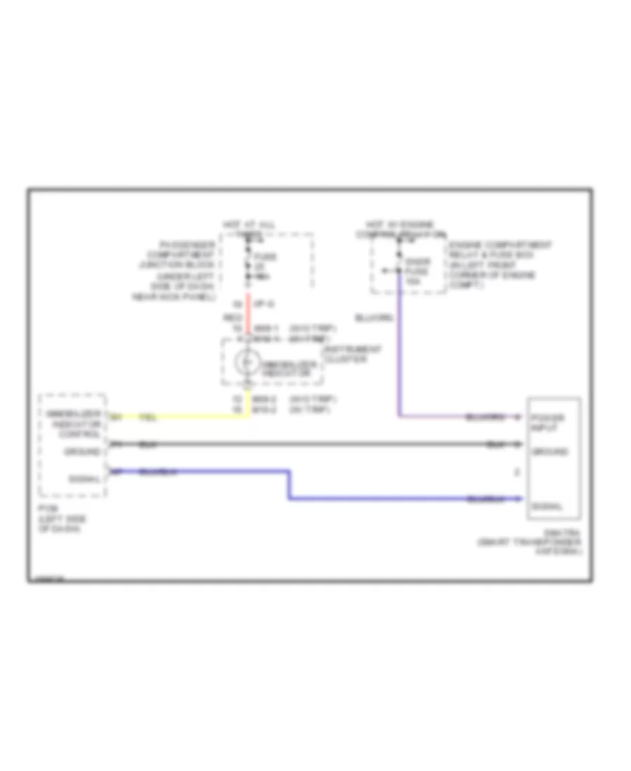
Immobilizer Wiring Diagram for Hyundai Elantra GT 2004
List of elements for Immobilizer Wiring Diagram for Hyundai Elantra GT 2004:
- (under left side of dash, near kick panel)
- (w/o trip) (w/ trip)
- Engine compartment relay & fuse box (in left front corner of engine compt)
- Fuse 15a
- Ground
- Hot at all times
- Hot w/ engine control relay on
- I/p-g
- Immobilizer indicator
- Immobilizer indicator control
- Instrument cluster
- M09-1 m10-1
- M09-2 m10-2
- Passenger compartment junction block
- Pcm (left side of dash)
- Power input
- Red
- Signal
- Smatra (smart transponder antenna)
- Snsr fuse 10a

 Čeština
 Dansk
Dansk Deutsch
 Ελληνικά
 English
 English
 Español
 Suomi
Suomi Français
 Français
 עברית
עברית Hrvatski
 Magyar
 Italiano
 日本語
日本語 한국어
한국어 Nederlands
 Polski
 Português
 Português
 Română
 Slovenčina
 Slovenščina
 Svenska
 Türkçe
 中文 (中国)