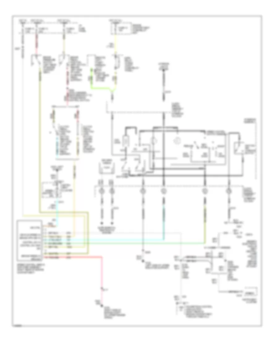
CRUISE CONTROL
Cruise Control Wiring Diagram for Ford Ranger 1998
List of elements for Cruise Control Wiring Diagram for Ford Ranger 1998:
- 20a
- 7.5a
- A/t
- Accel
- Brake pedal position (bpp) switch (behind left side of dash, on brake pedal support)
- Brake press in
- Brake pressure switch (left rear of engine compart- ment)
- C111
- C214
- C215
- C219
- C221
- C224
- C409
- Clock- spring assembly (top of steering column)
- Clutch pedal position (cpp) switch (behind left side of dash, top of clutch pedal support)
- Clutch pedal position (cpp) switch jumper (behind dash, left of steering column)
- Coast
- Control sw gnd
- Control sw in
- Driver's airbag
- Engine compartment fuse/relay box
- Fuse 10
- Fuse 10 15a
- Fuse 13
- Fuse 9
- G105 (right side of engine compt, on upper fender apron)
- G108 (left side of upper radiator support)
- Generic electronic module (gem)/ central timer module (ctm) (behind center of dash)
- Ground
- Horn nca switches
- Horn relay (in eng compt fuse/relay panel)
- Hot at all times
- Hot in run
- I/p fuse panel
- Ign
- Ignition key warning switch
- Ind ctrl
- Instru- ment cluster
- Instrument cluster
- Interior lights system
- M/t
- Main light switch
- Nca
- Off
- Ohms
- Powertrain control module (pcm) (right rear of engine compartment, through firewall)
- Remote anti- theft person- ality (rap) module (left rear corner of cab)
- Resume
- S117
- S139 (dash to head- lamp harn)
- S205
- S227
- S228 (main harness, near breakout to transmission control switch)
- S229 (main harness, behind top left side of dash)
- Set/
- Speed control ind
- Speed control servo/ amplifier assembly (right rear of engine compartment)
- Speed control switch assembly
- Speedo
- Steering assembly
- Vehicle speed in
- Vss in
- W/ 4wabs
- W/rabs
 Čeština
 Dansk
Dansk Deutsch
 Ελληνικά
 English
 English
 Español
 Suomi
Suomi Français
 עברית
עברית Hrvatski
 Magyar
 Italiano
 日本語
日本語 한국어
한국어 Nederlands
 Polski
 Português
 Português
 Română
 Русский
 Slovenčina
 Slovenščina
 Svenska
 Türkçe
 中文 (中国)
 Français