TRANSMISSION
2.5L
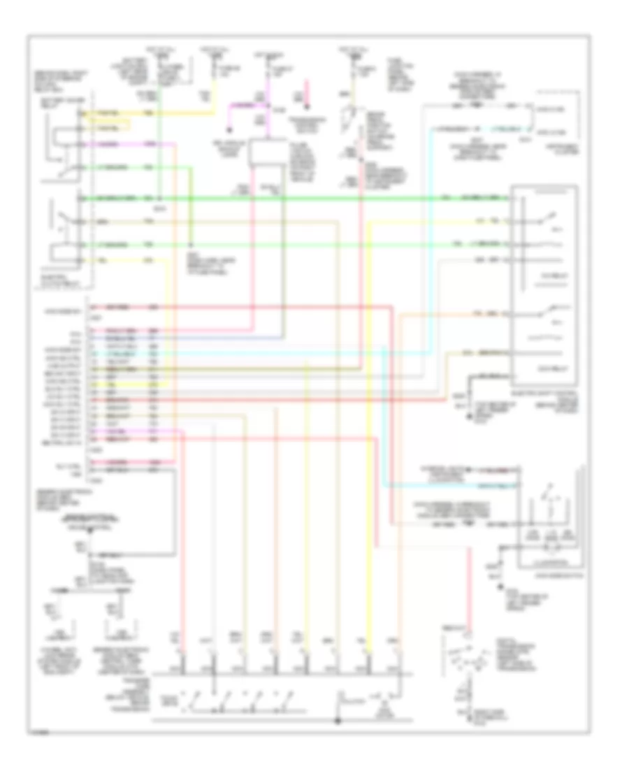
2.5L, Transmission Wiring Diagram, 4R44E for Ford Ranger 1998
 https://portal-diagnostov.com/license.html
Automotive Electricians Portal FZCO
Automotive Electricians Portal FZCO
https://portal-diagnostov.com/license.html
https://portal-diagnostov.com/license.html
Automotive Electricians Portal FZCO
Automotive Electricians Portal FZCO
List of elements for 2.5L, Transmission Wiring Diagram, 4R44E for Ford Ranger 1998:
- (dash panel to headlamp junction harness, near breakout to left headlamp) s121
- (engine control sensor extension harness, near breakout to harness in-line connector, left rear of engine)
- (engine control sensor harness, near breakout to ground g123)
- (engine control sensor harness, near breakout to intake air temp (iat) sensor)
- (left side of radiator support) g108
- (right side of firewall) g123
- 4-wheel anti- lock brake system module (left front of eng compt)
- 4r44e automatic transmission (left side of transmission)
- 4wabs
- Battery junction box
- Battery junction box (left rear of engine compt)
- Bpp
- Brake pedal position switch (on brake pedal support)
- C111
- C214
- C216
- Ccs
- Coast clutch solenoid (css)
- Cse gnd
- Data link connector (dlc) (partial) (fastened to bottom of dash, near steering column)
- Digital transmission range sensor (left side of trans)
- Dlc
- Dlc (+)
- Dlc (-)
- Drl module, back-up lamps, transfer case system
- Ect
- Electronic pressure control (epc) solenoid
- Engine controls (cmp sensor, h2os sensor, evr solenoid)
- Engine controls (ignition coil, radio noise capacitor)
- Engine controls system
- Engine coolant temperature (ect) sensor (top right front of eng, in water outlet tube)
- Epc
- Evap canister vent solenoid
- Fuse 19 25a
- Fuse 27 15a
- Fuse 9 7.5a
- Fuse junction panel (behind left side of dash)
- G108 (left side of upper radiator support)
- Generic electronic module (gem)/ central timer module (ctm) (center of dash)
- Hot at all times
- Hot in run
- Hot in start or run
- Instrument cluster
- Instrument cluster, cruise control
- Kapwr
- Malfunction indicator lamp (mil)
- Mil
- O/d off
- Pcm memory fuse 6 10a
- Pcm power diode
- Pcm power fuse 8 30a
- Pcm power relay
- Pcm/hego fuse 13 15a
- Power
- Powertrain control module (pcm) (right rear of engine compartment, through firewall)
- Pwr gnd
- R p
- Rabs
- Red
- S100 (engine control sensor harness, near breakout to intake air temp (iat) sensor)
- S1002
- S102
- S103
- S104 (engine control sensor harness, near breakout to ground g123, right side of firewall)
- S106
- S109 (engine control sensor harness, near left rear of engine)
- S118
- S139 (dash panel to headlamp junction harn)
- S228 (main harn, near breakout to tcs)
- Shift solenoid (ss1)
- Shift solenoid (ss2)
- Shift solenoid (ss3)
- Sig rtn
- Ss1
- Ss2
- Ss3
- Tcc
- Tcil
- Tcs
- Tft
- Throttle position (tp) sensor (top right side of engine, on throttle body)
- Torque converter clutch (tcc) solenoid
- Tr1
- Tr2
- Tr4
- Transmission control indicator lamp (tcil)
- Transmission control switch (tcs)
- Transmission fluid temperature (tft) sensor
- Tss
- Turbine shaft speed (tss) sensor
- Vref
- Vss
- Vss output
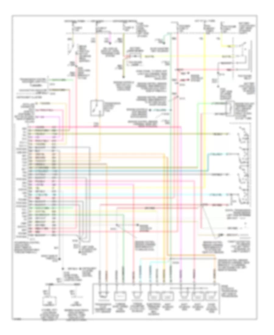
Transfer Case Wiring Diagram for Ford Ranger 1998
 https://portal-diagnostov.com/license.html
Automotive Electricians Portal FZCO
Automotive Electricians Portal FZCO
https://portal-diagnostov.com/license.html
https://portal-diagnostov.com/license.html
Automotive Electricians Portal FZCO
Automotive Electricians Portal FZCOList of elements for Transfer Case Wiring Diagram for Ford Ranger 1998:
- (behind dash, right side of steering column) relay box
- (main harness, in breakout to generic electronic module (gem) connectors)
- (main harness, near breakout to dash fuse panel)
- (top center of left fender apron) g104
- 1.1k ohms
- 3.9k ohms
- 4 wheel drive fuse 3 20a
- 4-wheel anti- lock brake system module (left front of eng compt)
- 4wabs
- 4wd hi ind
- 4wd ind ctrl
- 4wd lo ind
- 4wd mode sw
- 4wd mode switch
- 4wd motor
- 4wd output
- Battery junction box (left rear of engine compt)
- Battery saver relay
- Boo sw input
- Brake pedal position switch (on brake pedal support)
- C214
- C221
- C223
- C224
- Ccw relay
- Ccw rly ctrl
- Clutch
- Cruise control
- Cw relay
- Cw rly ctrl
- Digital transmission range (dtr) sensor (left side of transmission)
- Drl module, backup lamps
- Elc rly ctrl
- Electric clutch relay
- Electric shift control module (behind center of dash)
- Engine controls, instrument cluster,
- Fuse 26 10a
- Fuse 27 15a
- Fuse 9 7.5a
- Fuse junction panel (behind left side of dash)
- G104 (top center of left fender apron)
- Generic electronic module (gem) (behind center of dash)
- Generic electronic module (gem)/ central timer module (ctm) (center of dash)
- Hot at all times
- Hot in run
- Illumination
- Instrument cluster
- Interior lights (instrument illumination)
- Nca
- Neutral sw in
- Of firewall) g123
- Ohms
- Pulse vacuum hublock solenoid (on right front of vehicle)
- Pvh
- Rabs
- Rly ctrl
- S107
- S126
- S139 (dash panel to headlamp junction harn)
- S209
- S215
- S216
- S218
- S221 (dash harn, near breakout to i/p fuse panel)
- S228 (main harness, near breakout to instrument cluster)
- S237
- Sw a input
- Sw b input
- Sw c input
- Sw d input
- Touch drive
- Transfer case assembly (below vehicle, behind transmission)
- Transmission control switch
- Vss
- Vss output
3.0L
3.0L, Transmission Wiring Diagram, 4R44E for Ford Ranger 1998
 https://portal-diagnostov.com/license.html
Automotive Electricians Portal FZCO
Automotive Electricians Portal FZCO
https://portal-diagnostov.com/license.html
https://portal-diagnostov.com/license.html
Automotive Electricians Portal FZCO
Automotive Electricians Portal FZCOList of elements for 3.0L, Transmission Wiring Diagram, 4R44E for Ford Ranger 1998:
- (dash panel to headlamp junction harness, near breakout to left headlamp)
- (engine control sensor extension harness, near breakout to harness in-line connector, left rear of engine)
- (engine control sensor harness, near breakout to ground g123)
- (engine control sensor harness, near breakout to ground g123, right side of firewall)
- (engine control sensor harness, near breakout to intake air temp (iat) sensor)
- (engine control sensor harness, near breakout to octane adjust shorting bar)
- (engine control sensor harness, near left rear of engine)
- (left side of radiator support) g108
- (right side of firewall) g123
- 4-wheel anti- lock brake system module (left front of eng compt)
- 4r44e automatic transmission (left side of transmission)
- 4wabs
- Battery junction box
- Battery junction box (left rear of engine compt)
- Bpp
- Brake pedal position switch (on brake pedal support)
- C111
- C214
- C216
- Ccs
- Coast clutch solenoid (css)
- Cse gnd
- Data link connector (dlc) (partial) (fastened to bottom of dash, near steering column)
- Digital transmission range sensor (left side of trans)
- Dlc
- Dlc (+)
- Dlc (-)
- Drl module, back-up lamps, transfer case system
- Ect
- Electronic pressure control (epc) solenoid
- Engine controls (cmp sensor, h2os sensor, evr solenoid)
- Engine controls (ignition coil, radio noise capacitor)
- Engine controls system
- Engine coolant temperature (ect) sensor (top right front of eng, in water outlet tube)
- Epc
- Evap canister vent solenoid
- Fuse 19 25a
- Fuse 27 15a
- Fuse 9 7.5a
- Fuse junction panel (behind left side of dash)
- G108 (left side of upper radiator support)
- Generic electronic module (gem)/ central timer module (ctm) (center of dash)
- Hot at all times
- Hot in run
- Hot in start or run
- Instrument cluster
- Instrument cluster, cruise control
- Kapwr
- Malfunction indicator lamp (mil)
- Mil
- O/d off
- Pcm memory fuse 6 10a
- Pcm power diode
- Pcm power fuse 8 30a
- Pcm power relay
- Pcm/hego fuse 13 15a
- Power
- Powertrain control module (pcm) (right rear of engine compartment, through firewall)
- Pwr gnd
- R p
- Rabs
- Red
- S100
- S1002
- S102
- S103
- S104
- S106
- S109
- S112
- S118
- S121
- S139 (dash panel to headlamp junction harn)
- S228 (main harn, near breakout to tcs)
- Shift solenoid (ss1)
- Shift solenoid (ss2)
- Shift solenoid (ss3)
- Sig rtn
- Ss1
- Ss2
- Ss3
- Tcc
- Tcil
- Tcs
- Tft
- Throttle position (tp) sensor (top left front of engine, on throttle body)
- Torque converter clutch (tcc) solenoid
- Tr1
- Tr2
- Tr4
- Transmission control indicator lamp (tcil)
- Transmission control switch (tcs)
- Transmission fluid temperature (tft) sensor
- Tss
- Turbine shaft speed (tss) sensor
- Vref
- Vss
- Vss output
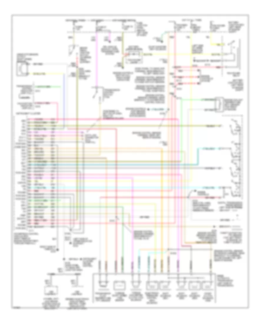
Transfer Case Wiring Diagram for Ford Ranger 1998
 https://portal-diagnostov.com/license.html
Automotive Electricians Portal FZCO
Automotive Electricians Portal FZCO
https://portal-diagnostov.com/license.html
https://portal-diagnostov.com/license.html
Automotive Electricians Portal FZCO
Automotive Electricians Portal FZCOList of elements for Transfer Case Wiring Diagram for Ford Ranger 1998:
- (behind dash, right side of steering column) relay box
- (main harness, in breakout to generic electronic module (gem) connectors)
- (main harness, near breakout to dash fuse panel)
- (top center of left fender apron) g104
- 1.1k ohms
- 3.9k ohms
- 4 wheel drive fuse 3 20a
- 4-wheel anti- lock brake system module (left front of eng compt)
- 4wabs
- 4wd hi ind
- 4wd ind ctrl
- 4wd lo ind
- 4wd mode sw
- 4wd mode switch
- 4wd motor
- 4wd output
- Battery junction box (left rear of engine compt)
- Battery saver relay
- Boo sw input
- Brake pedal position switch (on brake pedal support)
- C214
- C221
- C223
- C224
- Ccw relay
- Ccw rly ctrl
- Clutch
- Cruise control
- Cw relay
- Cw rly ctrl
- Digital transmission range (dtr) sensor (left side of transmission)
- Drl module, backup lamps
- Elc rly ctrl
- Electric clutch relay
- Electric shift control module (behind center of dash)
- Engine controls, instrument cluster,
- Fuse 26 10a
- Fuse 27 15a
- Fuse 9 7.5a
- Fuse junction panel (behind left side of dash)
- G104 (top center of left fender apron)
- Generic electronic module (gem) (behind center of dash)
- Generic electronic module (gem)/ central timer module (ctm) (center of dash)
- Hot at all times
- Hot in run
- Illumination
- Instrument cluster
- Interior lights (instrument illumination)
- Nca
- Neutral sw in
- Of firewall) g123
- Ohms
- Pulse vacuum hublock solenoid (on right front of vehicle)
- Pvh
- Rabs
- Rly ctrl
- S107
- S126
- S139 (dash panel to headlamp junction harn)
- S209
- S215
- S216
- S218
- S221 (dash harn, near breakout to i/p fuse panel)
- S228 (main harness, near breakout to instrument cluster)
- S237
- Sw a input
- Sw b input
- Sw c input
- Sw d input
- Touch drive
- Transfer case assembly (below vehicle, behind transmission)
- Transmission control switch
- Vss
- Vss output
4.0L
4.0L, Transmission Wiring Diagram, 5R55E for Ford Ranger 1998
 https://portal-diagnostov.com/license.html
Automotive Electricians Portal FZCO
Automotive Electricians Portal FZCO
https://portal-diagnostov.com/license.html
https://portal-diagnostov.com/license.html
Automotive Electricians Portal FZCO
Automotive Electricians Portal FZCOList of elements for 4.0L, Transmission Wiring Diagram, 5R55E for Ford Ranger 1998:
- (dash panel to headlamp harness, near breakout to left headlamp)
- (engine control sensor extension harness, near breakout to harness in-line connector, left rear of engine)
- (engine control sensor harness, near breakout to fuel inj 6)
- (engine control sensor harness, near breakout to fuel injector 5)
- (engine control sensor harness, near breakout to mass air flow sensor)
- (engine control sensor harness, near breakout to powertrain control module)
- (engine control sensor harness, near left rear of engine)
- (fastened to bottom of dash, right of steering column)
- (left side of upper radiator support)
- (left side of upper radiator support) g108
- (near dtr sensor) output shaft speed sensor
- (right side of firewall) g123
- 4-wheel anti- lock brake system module (left front of eng compt)
- 4wabs
- 5r55e automatic transmission (left side of transmission)
- Battery junction box
- Battery junction box (left rear of engine compt)
- Bpp
- Brake pedal position switch (on brake pedal support)
- C111
- C214
- C216
- Case gnd
- Ccs
- Coast clutch solenoid (css)
- Connector (dlc) (partial)
- Data link
- Digital transmission range sensor (left side of trans)
- Dlc
- Dlc (+)
- Dlc (-)
- Drl module, backup lamps, transfer case system
- Ect
- Electronic pressure control (epc) solenoid
- Engine controls
- Engine controls (cmp sensor, h2os sensor, evr solenoid)
- Engine controls (ignition coil, radio noise capacitor)
- Engine controls system
- Engine coolant temperature (ect) sensor (top front of engine)
- Epc
- Evap canister vent solenoid
- Fuse 19 25a
- Fuse 27 15a
- Fuse 9 7.5a
- Fuse junction panel (behind left side of dash)
- G108
- Generic electronic module (gem)/ central timer module (ctm) (center of dash)
- Hot at all times
- Hot in run
- Hot in start or run
- Instrument cluster
- Instrument cluster, cruise control
- Kapwr
- Malfunction indicator lamp (mil)
- Mil
- O/d off
- Oss
- Pcm memory fuse 6 10a
- Pcm power diode
- Pcm power fuse 8 30a
- Pcm power relay
- Pcm/hego fuse 13 15a
- Power
- Powertrain control module (pcm) (right rear of engine compartment, through firewall)
- Pwr gnd
- R p
- Rabs
- Red
- S100 (engine control sensor harness, near breakout to intake air temp (iat) sensor)
- S1002
- S102 (eng ctrl harn, near breakout to diff press feedback sensor)
- S103
- S104
- S106
- S109
- S112
- S113
- S118
- S121
- S139 (dash panel to headlamp junction harn)
- S228 (main harn, near breakout to tcs)
- Shift solenoid (ss1)
- Shift solenoid (ss2)
- Shift solenoid (ss3)
- Sig rtn
- Ss1
- Ss2
- Ss3
- Tcc
- Tcil
- Tcs
- Tft
- Throttle position (tp) sensor (top left front of engine, on throttle body)
- Torque converter clutch (tcc) solenoid
- Tr1
- Tr2
- Tr4
- Transmission control indicator lamp (tcil)
- Transmission control switch (tcs)
- Transmission fluid temperature (tft) sensor
- Tss
- Turbine shaft speed (tss) sensor
- Vref
- Vss
- Vss output
Transfer Case Wiring Diagram for Ford Ranger 1998
 https://portal-diagnostov.com/license.html
Automotive Electricians Portal FZCO
Automotive Electricians Portal FZCO
https://portal-diagnostov.com/license.html
https://portal-diagnostov.com/license.html
Automotive Electricians Portal FZCO
Automotive Electricians Portal FZCOList of elements for Transfer Case Wiring Diagram for Ford Ranger 1998:
- (behind dash, right side of steering column) relay box
- (main harness, in breakout to generic electronic module (gem) connectors)
- (main harness, near breakout to dash fuse panel)
- (top center of left fender apron) g104
- 1.1k ohms
- 3.9k ohms
- 4 wheel drive fuse 3 20a
- 4-wheel anti- lock brake system module (left front of eng compt)
- 4wabs
- 4wd hi ind
- 4wd ind ctrl
- 4wd lo ind
- 4wd mode sw
- 4wd mode switch
- 4wd motor
- 4wd output
- Battery junction box (left rear of engine compt)
- Battery saver relay
- Boo sw input
- Brake pedal position switch (on brake pedal support)
- C214
- C221
- C223
- C224
- Ccw relay
- Ccw rly ctrl
- Clutch
- Cruise control
- Cw relay
- Cw rly ctrl
- Digital transmission range (dtr) sensor (left side of transmission)
- Drl module, backup lamps
- Elc rly ctrl
- Electric clutch relay
- Electric shift control module (behind center of dash)
- Engine controls, instrument cluster,
- Fuse 26 10a
- Fuse 27 15a
- Fuse 9 7.5a
- Fuse junction panel (behind left side of dash)
- G104 (top center of left fender apron)
- Generic electronic module (gem) (behind center of dash)
- Generic electronic module (gem)/ central timer module (ctm) (center of dash)
- Hot at all times
- Hot in run
- Illumination
- Instrument cluster
- Interior lights (instrument illumination)
- Nca
- Neutral sw in
- Of firewall) g123
- Ohms
- Pulse vacuum hublock solenoid (on right front of vehicle)
- Pvh
- Rabs
- Rly ctrl
- S107
- S126
- S139 (dash panel to headlamp junction harn)
- S209
- S215
- S216
- S218
- S221 (dash harn, near breakout to i/p fuse panel)
- S228 (main harness, near breakout to instrument cluster)
- S237
- Sw a input
- Sw b input
- Sw c input
- Sw d input
- Touch drive
- Transfer case assembly (below vehicle, behind transmission)
- Transmission control switch
- Vss
- Vss output

 Čeština
 Dansk
Dansk Deutsch
 Ελληνικά
 English
 English
 Español
 Suomi
Suomi Français
 Français
 עברית
עברית Hrvatski
 Magyar
 Italiano
 한국어
한국어 Nederlands
 Polski
 Português
 Português
 Română
 Русский
 Slovenčina
 Slovenščina
 Svenska
 Türkçe
 中文 (中国)
