БЛОК ПРЕДОХРАНИТЕЛЕЙ И РЕЛЕ
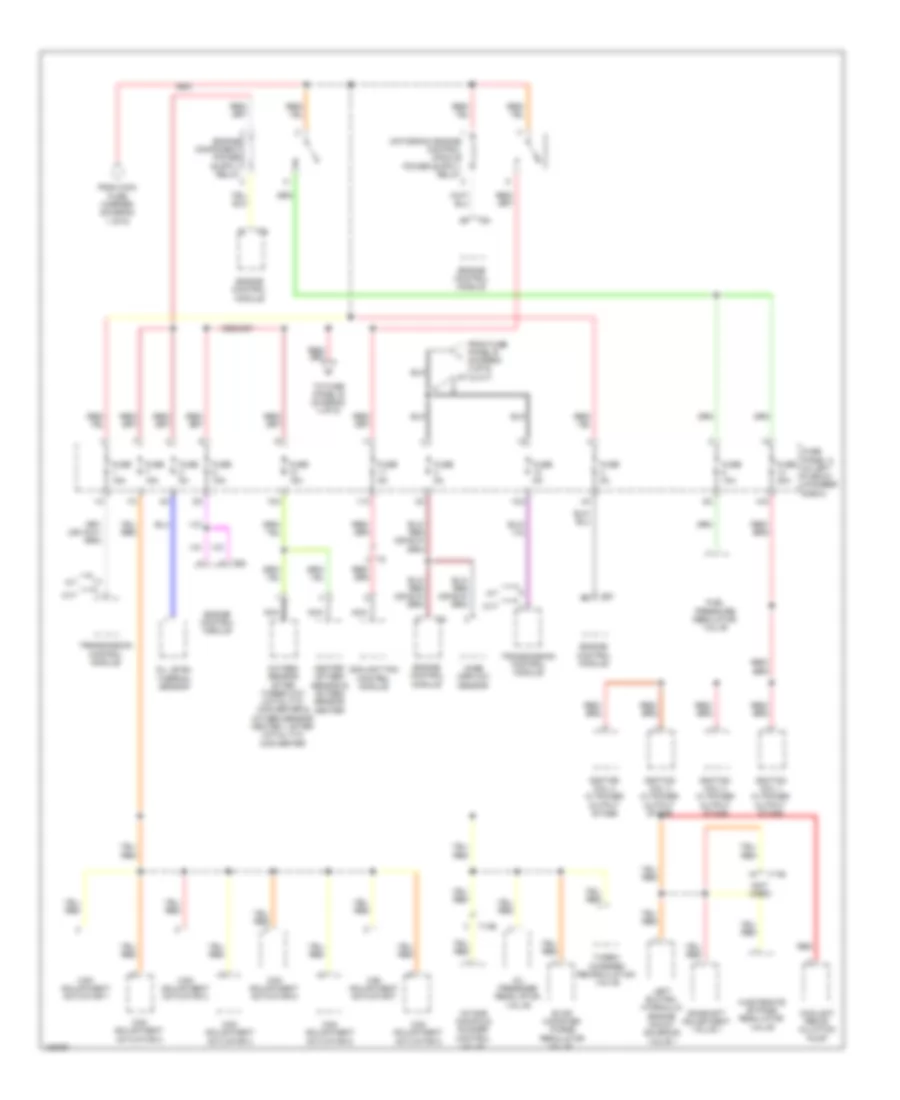
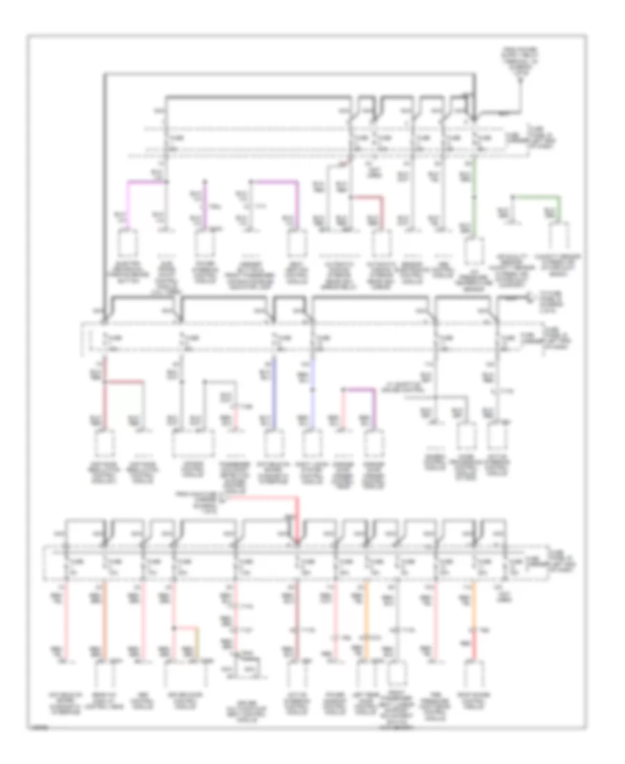
Электросхема блока предохранителей и реле (1 из 9) для Audi A6 Premium Plus 2013

Электросхема блока предохранителей и реле (1 из 9) для Audi A6 Premium Plus 2013 - Список элементов:
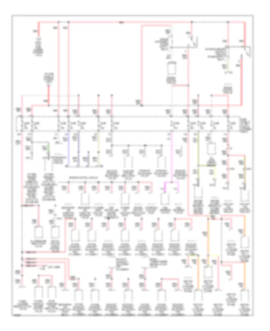
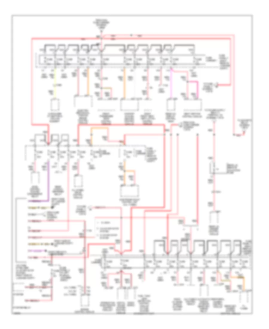
Электросхема блока предохранителей и реле (2 из 9) для Audi A6 Premium Plus 2013
Электросхема блока предохранителей и реле (2 из 9) для Audi A6 Premium Plus 2013 - Список элементов:
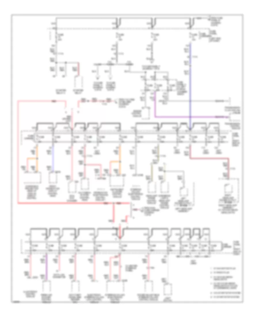
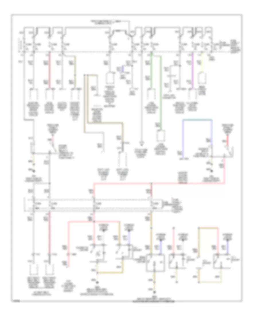
Электросхема блока предохранителей и реле (3 из 9) для Audi A6 Premium Plus 2013
Электросхема блока предохранителей и реле (3 из 9) для Audi A6 Premium Plus 2013 - Список элементов:
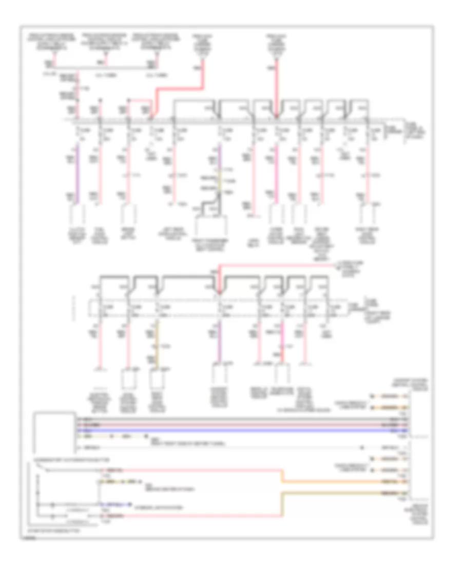
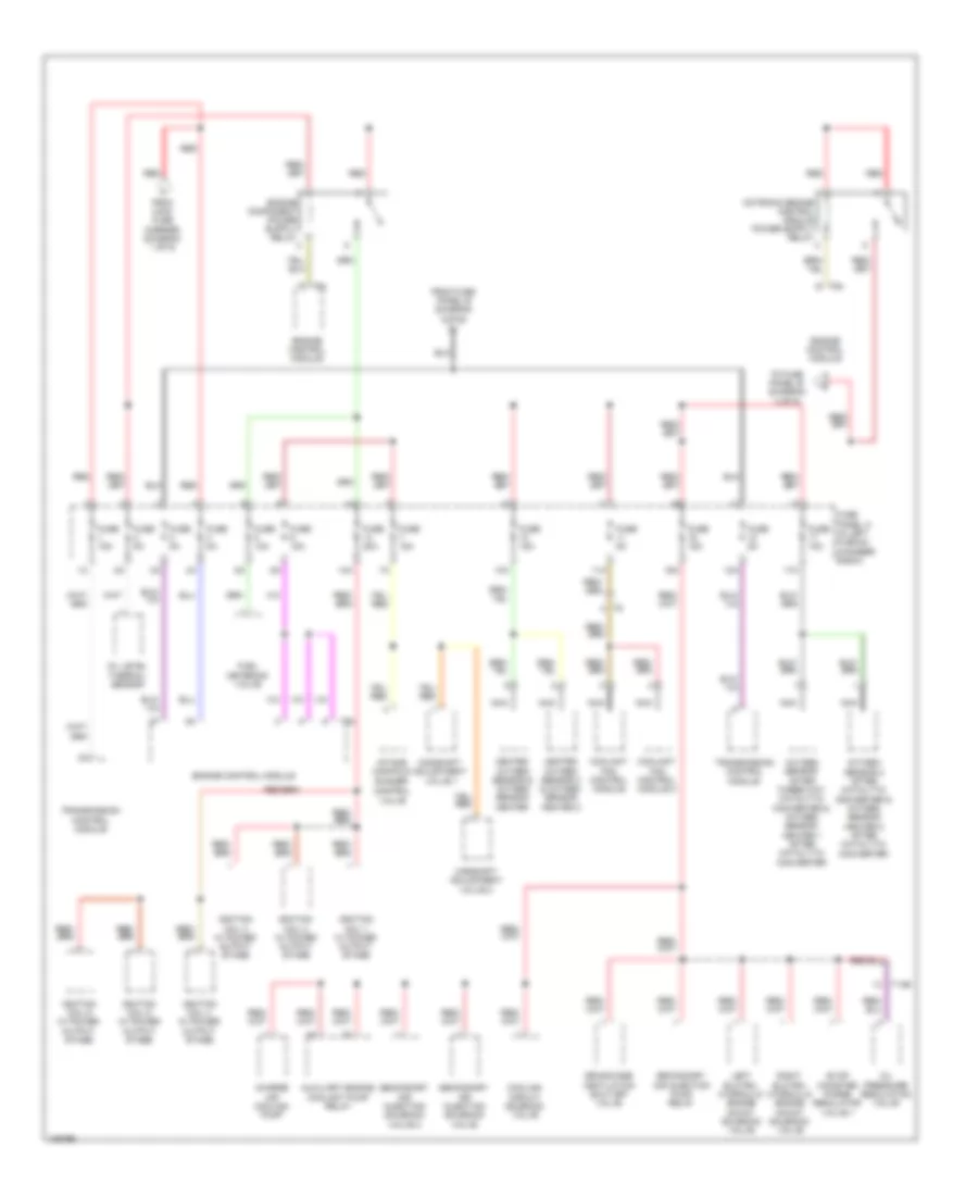
Электросхема блока предохранителей и реле (4 из 9) для Audi A6 Premium Plus 2013
Электросхема блока предохранителей и реле (4 из 9) для Audi A6 Premium Plus 2013 - Список элементов:
Электросхема блока предохранителей и реле (5 из 9) для Audi A6 Premium Plus 2013
Электросхема блока предохранителей и реле (5 из 9) для Audi A6 Premium Plus 2013 - Список элементов:
Электросхема блока предохранителей и реле (6 из 9) для Audi A6 Premium Plus 2013
Электросхема блока предохранителей и реле (6 из 9) для Audi A6 Premium Plus 2013 - Список элементов:
Электросхема блока предохранителей и реле (7 из 9) для Audi A6 Premium Plus 2013
Электросхема блока предохранителей и реле (7 из 9) для Audi A6 Premium Plus 2013 - Список элементов:
Электросхема блока предохранителей и реле (8 из 9) для Audi A6 Premium Plus 2013
Электросхема блока предохранителей и реле (8 из 9) для Audi A6 Premium Plus 2013 - Список элементов:
Электросхема блока предохранителей и реле (9 из 9) для Audi A6 Premium Plus 2013
Электросхема блока предохранителей и реле (9 из 9) для Audi A6 Premium Plus 2013 - Список элементов: