СИСТЕМА ОХЛАЖДЕНИЯ
Электросхема системы охлаждения для Audi A6 Premium Plus 2013
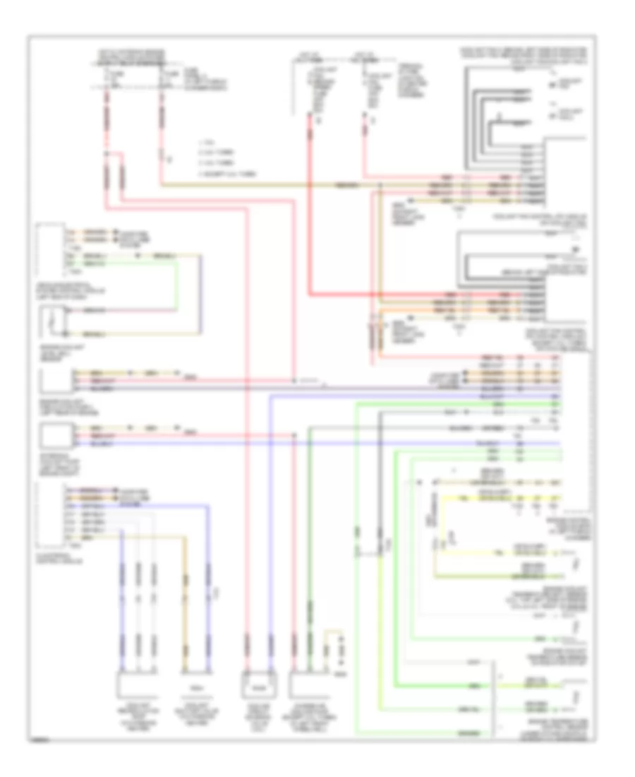
Электросхема системы охлаждения для Audi A6 Premium Plus 2013 - Список элементов:
- (coolant fan 2: behind left side of radiator) (coolant fan: behind right side of radiator) coolant fan/coolant fan 2
- (or red)
- 11a
- 16a
- 2.0l turbo
- 3.0l
- 4.0l turbo
- After-run coolant pump (left front of engine compt)
- Charge air cooling pump (except 2.0l turbo) (in left front wheelwell)
- Climatronic control module
- Computer data lines system
- Coolant fan
- Coolant fan 2
- Coolant fan 2 (behind left side of radiator)
- Coolant fan control (fc) control module 2 (except 2.0l turbo) (on coolant fan 2)
- Coolant fan control (fc) module (on coolant fan)
- Coolant fan fuse 40a/ 60a/ 80a
- Coolant fan second speed fuse 40a/ 60a/ 80a
- Coolant recirculation pump (w/o parking heater)
- Coolant shut-off valve (w/o parking heater)
- Cooling circuit solenoid valve (3.0l)
- Engine control module (ecm) (in left plenum chamber)
- Engine coolant circulation pump 2 (left rear of engine)
- Engine coolant level (ecl) sensor
- Engine coolant temperature (ect) sensor (2.0l: top left side of engine) (3.0l & 4.0l: front of engine)
- Engine coolant temperature sensor on radiator outlet
- Engine temperature control sensor (under intake manifold, on right cylinder bank)
- Except 2.0l turbo
- Fuse 15a
- Fuse 5a
- Fuse panel a (in left plenum chamber e-box)
- G645
- G685 (on right front long member)
- Hot at all times
- Nca
- Red
- T105
- T14a
- T14b
- T16c
- T17i
- T20c
- T32a
- T4fm
- T4fn
- T60
- T91
- T94
- Terminal 30 wire junction (in center plenum chamber)
- Vehicle electrical system control module (left end of dash)
 Русский