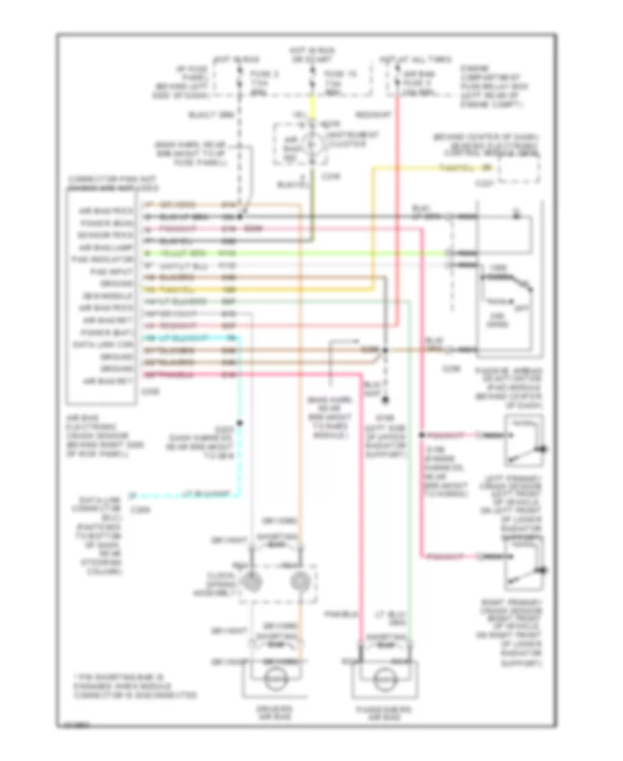
SUPPLEMENTAL RESTRAINTS
Supplemental Restraint Wiring Diagram for Ford Ranger 1998
List of elements for Supplemental Restraint Wiring Diagram for Ford Ranger 1998:
- (behind center of dash) generic electronic control module (gem)
- (dlc) (fastened to bottom of dash, near steering column)
- (engine harness, near breakout to horns)
- (left side of upper radiator support)
- (main harn, near breakout to rabs module)
- (main harn, near breakout to i/p fuse panel)
- * pin shorting bar is engaged when module connector is disconnected
- Air bag electronic crash sensor (behind right side of kick panel)
- Air bag feed
- Air bag fuse 5 10a mini
- Air bag ind
- Air bag lamp
- Air bag ret
- C216
- C221
- C250
- C256
- Clock- spring assembly
- Connector pins not shown are not used
- Data link con
- Data link connector c209
- Driver's air bag
- Engine compartment fuse/relay box (left rear of engine compt)
- Fuse 15 7.5a mini
- Fuse 2 7.5a mini
- G108
- Gem module
- Ground
- Hot at all times
- Hot in run
- Hot in run or start
- I/p fuse panel (behind left side of dash)
- Instrument cluster
- Left primary crash sensor (left front of vehicle, on left front of lower radiator support)
- Nca
- Off
- Ohms
- Pad indicator
- Pad input
- Passenger's air bag
- Passive airbag deactivation (pad) module (behind center of dash)
- Power (bat)
- Power (run)
- Right primary crash sensor (right front of vehicle, on right front of lower radiator
- S156
- S205
- S225 dash harness, near breakout to gem
- S250
- Sensor feed
- Shorting bar
- Support)
 Čeština
 Dansk
Dansk Deutsch
 Ελληνικά
 English
 English
 Español
 Suomi
Suomi Français
 Français
 עברית
עברית Hrvatski
 Magyar
 Italiano
 日本語
日本語 한국어
한국어 Nederlands
 Português
 Português
 Română
 Русский
 Slovenčina
 Slovenščina
 Svenska
 Türkçe
 中文 (中国)
 Polski