СИСТЕМА ПЕРЕДАЧИ ДАННЫХ
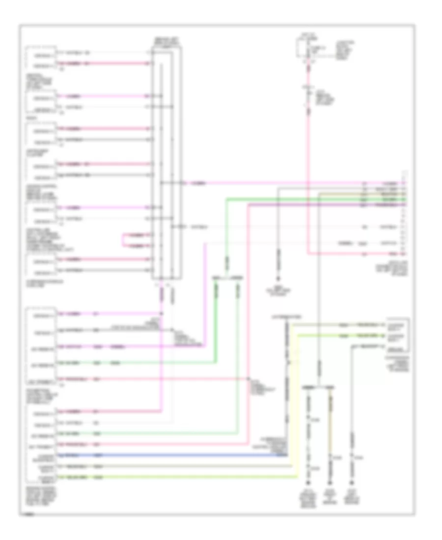
Электросхема компьютерной линии передачи данных CAN для Dodge Cab amp; Chassis R2500 2002
Электросхема компьютерной линии передачи данных CAN для Dodge Cab amp; Chassis R2500 2002 - Список элементов:
- (behind left side of dash) j/c 7
- (diesel)
- (drain wire)
- (gas)
- (in breakout to engine control module) (diesel) s184
- (unterminated)
- A cummins bus (+)
- Air bag control module (behind lower center of dash)
- B cummins bus (-)
- Ccd bus (+)
- Ccd bus (-)
- Central timer module (on left side of dash)
- Controller anti-lock brake (rwal: left front inner fender) (4wabs: mounted on hydraulic control unit)
- Cummins bus (+)
- Cummins bus (-)
- Cummins bus (diesel) (left front of engine)
- Cummins bus shield
- D20
- D21
- D220
- Data link connector (dlc) (on left bottom of dash)
- Diesel
- Engine control module (on left side of engine, behind fuel filter)
- Fuse 12 10a
- G105 (front of engine)
- G107 (left rear of engine)
- G113 (primary battery engine ground)
- G200 (on left end of dash)
- Gas
- Ground
- Hot at all times
- Instrument cluster
- J/c 5 (behind left side of dash)
- Junction block (on left end of dash)
- K244
- K246
- K247
- Nca
- Overhead console (highline)
- Pnk
- Powertrain control module (on right side of firewall)
- Radio
- S109
- S126
- S164
- S172 (diesel) (top of a/c accumulator)
- S173 (diesel) (top of a/c accumulator)
- S175 (diesel) (in breakout to pdc)
- Sci receive
- Sci transmit
- Z11
- Z12
 Русский